2 layers249 × 180.3 mm
Kicad snapshot step16 rev a layout complete 20260324 150352
jgrano/Nx-PCBA
Install all of these before opening the project:
91 parts
 IPrometheusI/buck-boost
Cargador solar buck-boost no inversor con control CC-CV en ESP32, simulación MATLAB/Simulink y diseño PCB en KiCad.
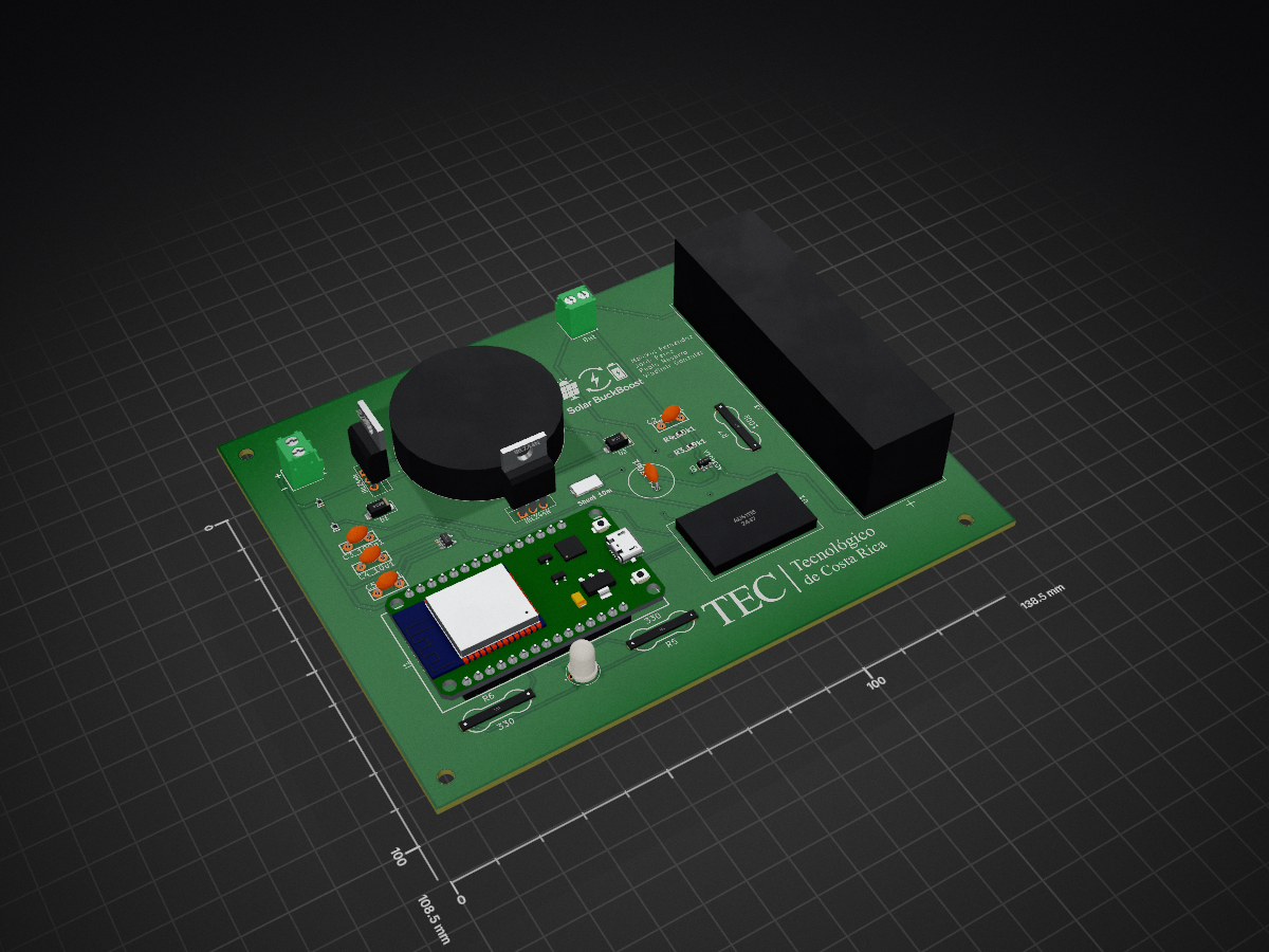
Buck boost is an open-source printed circuit board by IPrometheusI, from the IPrometheusI/buck-boost repository on GitHub, published under the MIT licence. It is a 2-layer board of 138.5 × 108.5 mm with 32 parts on 41 nets, routed with 162 tracks and 8 vias.
It is built around the ADS1115, AP2112K-3.3TRG1 and IRLZ44N, with the SS34, AO3401A and ECA-1HHG471B among its other parts. Its parts include 7 resistors, 5 capacitors, 3 diodes, 3 transistors and 3 connectors. It belongs with the power boards and the ESP32 boards of this library.






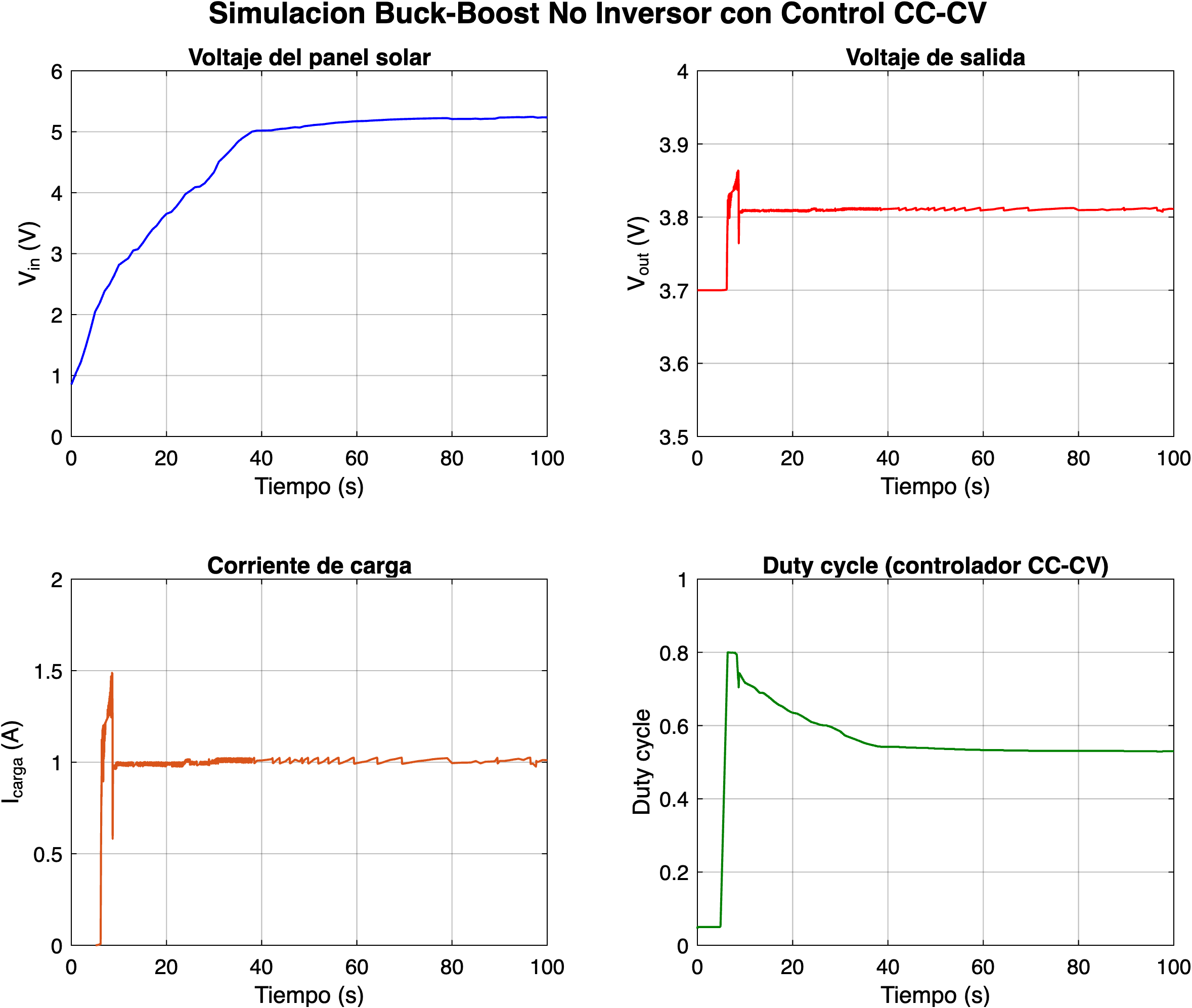
Cargador de baterías Li-ion utilizando un convertidor DC/DC Buck-Boost no inversor alimentado por un panel solar de 6W, con control CC-CV (Corriente Constante -- Voltaje Constante) implementado en un ESP32.
| Parámetro | Valor |
|---|---|
| Batería | Li-ion 3.7V / 6000mAh |
| Voltaje de carga máximo | 4.2V |
| Corriente de carga (CC) | ~1.0A promedio |
| Panel solar | 6V / 6W, Vmpp real ~5.5V |
| Inductor | Bourns 1140-102K-RC, 1mH |
| Capacitor | Panasonic ECA-1HHG471B, 470uF/50V |
| Frecuencia PWM | 30kHz |
| Microcontrolador | ESP32-DevKit V1 |
| ADC externo | ADS1115 (16-bit, I2C) |
| Rshunt | 10mOhm (ROHM GMR100HJBFA10L0) |
El convertidor utiliza una topología buck-boost no inversora con dos MOSFETs (Q1, Q2) y dos diodos Schottky (D1, D2), manteniendo la polaridad positiva en la salida para conectar la batería directamente.
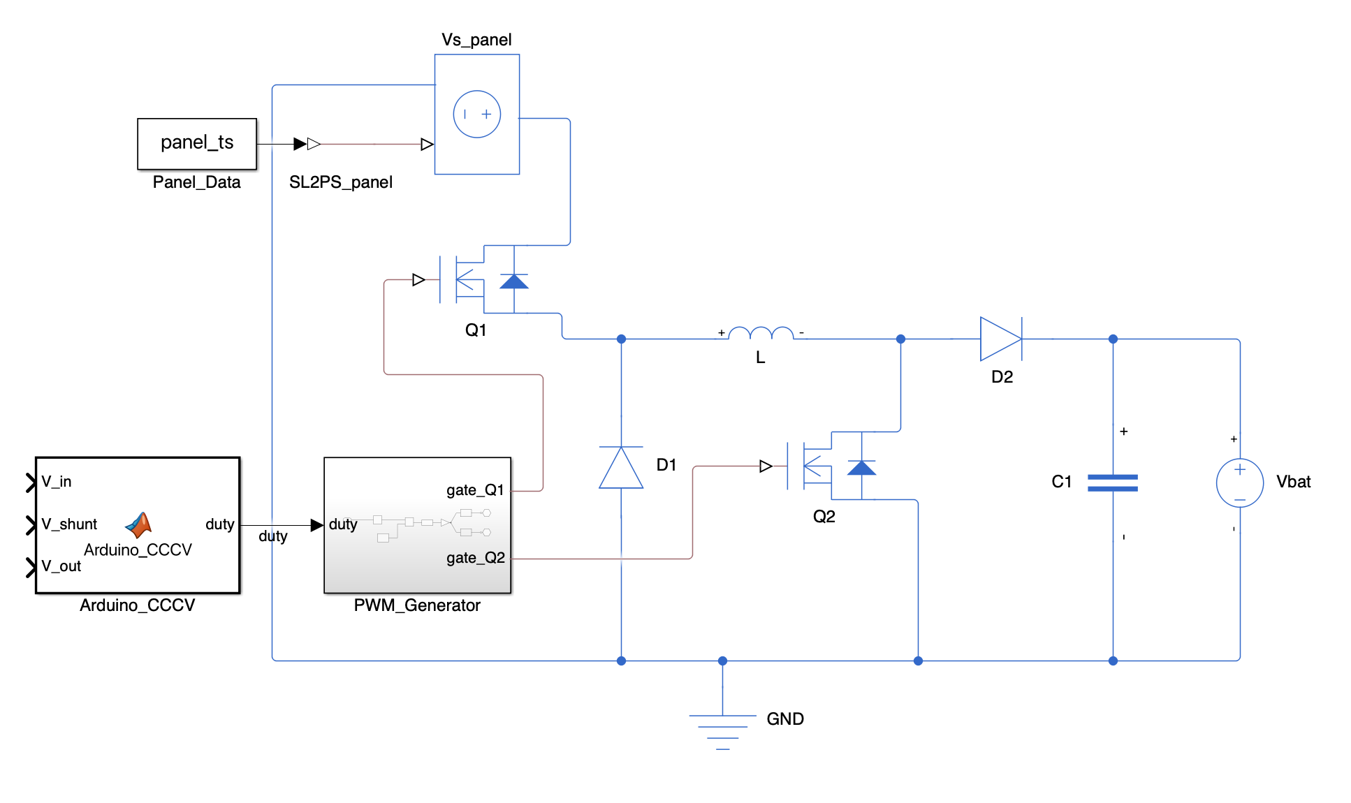
La relación de conversión ideal es:
$$V_{out} = V_{in} \cdot \frac{D}{1 - D}$$
El algoritmo de carga opera en tres modos con prioridad descendente:
La corriente se mide con una resistencia shunt de 10mOhm y el ADS1115 en modo diferencial (resolucion ~0.78 mA/bit).
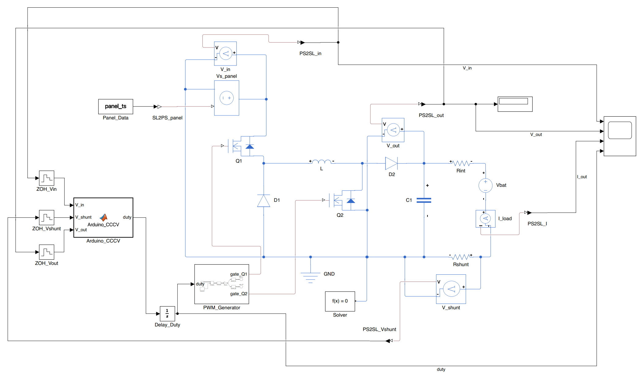
El modelo en Simulink utiliza datos reales de irradiancia solar (779 muestras, 9 mayo 2024) y emula el controlador CC-CV del ESP32.
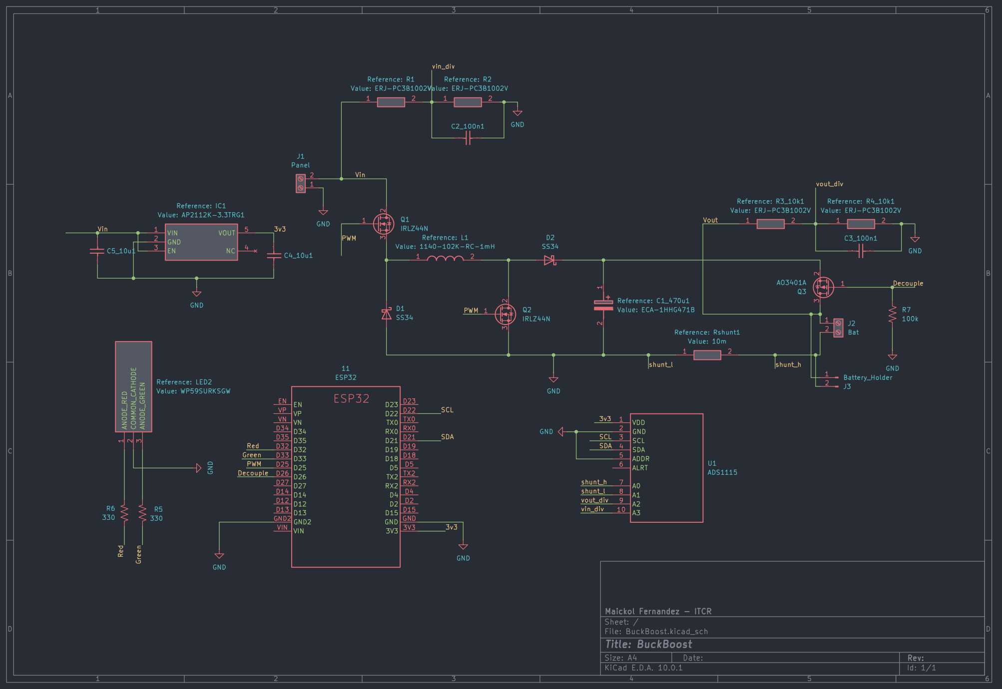
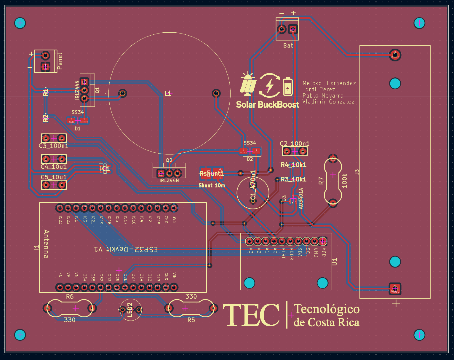
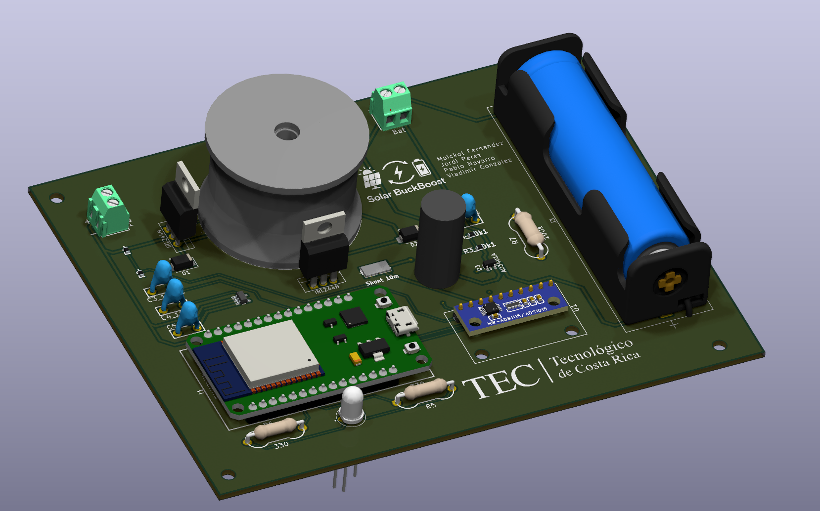
Instituto Tecnologico de Costa Rica -- I Semestre 2024
Este proyecto esta bajo la Licencia MIT.
| Qty | Value | Footprint | References |
|---|---|---|---|
| 4 | ERJ-PC3B1002V | Samacsys:ERJPC3D9763V | R1, R2, R3_10k1, R4_10k1 |
| 4 | MountingHole_3.2mm_M3 | MountingHole:MountingHole_3.2mm_M3 | REF1, REF2, REF3, REF4 |
| 4 | ~ | 1_KiCad_Personal_Lib:CeramicCapacitor | C2_100n1, C3_100n1, C4_10u1, C5_10u1 |
| 2 | 330 | 1_KiCad_Personal_Lib:ResistorThroughHole | R5, R6 |
| 2 | IRLZ44N | Package_TO_SOT_THT:TO-220-3_Vertical | Q1, Q2 |
| 2 | LOGO | LOGO | G***, G1 |
| 2 | SS34 | Diode_SMD:D_SMA | D1, D2 |
| 1 | 100k | 1_KiCad_Personal_Lib:ResistorThroughHole | R7 |
| 1 | 10m | Samacsys:GMR100HJBFA10L0 | Rshunt1 |
| 1 | 1140-102K-RC-1mH | 2_Samacsys_V2:1140102KRC | L1 |
| 1 | ADS1115 | 1_KiCad_Personal_Lib:ADC-4CH-ADS1115 | U1 |
| 1 | AO3401A | Package_TO_SOT_SMD:SOT-23 | Q3 |
| 1 | AP2112K-3.3TRG1 | 2_Samacsys_V2:SOT95P285X140-5N | IC1 |
| 1 | Bat | 1_KiCad_Personal_Lib:SCREWTERMINAL-3.5MM-2 | J2 |
| 1 | Battery_Holder | Battery:BatteryHolder_MPD_BH-18650-PC | J3 |
| 1 | ECA-1HHG471B | Samacsys:CAPPRD500W65D1000H2200 | C1_470u1 |
| 1 | ESP32 | 1_KiCad_Personal_Lib:ESP32-DEVKITV1_ESP32-DEVKITV1 | I1 |
| 1 | Panel | 1_KiCad_Personal_Lib:SCREWTERMINAL-3.5MM-2 | J1 |
| 1 | WP59SURKSGW | Samacsys:WP59EGC | LED2 |
It measures 138.5 × 108.5 mm and has 2 copper layers, 1.6 mm thick.
32 parts, built around the ADS1115, AP2112K-3.3TRG1, IRLZ44N and SS34. The full list of its parts is on this page, with links to each part's symbol and footprint where PCBKit's library has them.
From the IPrometheusI/buck-boost repository on GitHub, at the commit this page was made from: the board is KiCad/BuckBoost/BuckBoost.kicad_pcb and its schematic KiCad/BuckBoost/BuckBoost.kicad_sch. PCBKit opens the board in the browser, with nothing to install.
Its repository publishes it under the MIT licence: you may reuse it on that licence's terms (keep the author's notice, and for a copyleft licence share your changes alike).
jgrano/Nx-PCBA
Install all of these before opening the project:

FujiNetWIFI/fujinet-hardware
Schematics and design files for FujiNet hardware

tschak909/frob-modern
The Frob, An Apple II Atari 2600 Development System, re-made as an RP2354 based device.

Diode663/ESP32_4-20mA_Sensor
Single-channel industrial 4-20 mA current-loop reader for ESPHome / Home Assistant. ESP32-S3 + INA226, USB-C powered, 24 V loop supply with a constant-current limiter. KiCad 10, generated from Python.


