4 layers163.8 × 237.4 mm
Modular rack power carrier6-backplane1-rev a
kquinsland/modular-rack-mount-power-system
Hardware, firmware, and host tooling for a modular mini-rack power system.
729 parts

 ionutms/Minimal_LT8304
This repository contains a minimal KiCad design project for the Analog Devices LT8304, a monolithic micropower isolated flyback converter.
Minimal LT8304 is an open-source printed circuit board by ionutms, from the ionutms/Minimal_LT8304 repository on GitHub, published under the MIT licence. It is a 4-layer board of 61 × 22.9 mm with 35 parts on 22 nets, routed with 12 tracks and 152 vias.
It is built around the PMEG10020AELRX, CRCW0603100RFKEAHP and CC0603JRNPO9BN221, with the C1206R105K3RAC7800, CL31B106KBHNNNE and C1210C472KFRACAUTO among its other parts. Its parts include 8 capacitors, 7 resistors, 4 diodes, 2 connectors and 1 IC.


This repository contains a minimal KiCad design project for the Analog Devices LT8304, a monolithic micropower isolated flyback converter. The project includes schematic designs and PCB layout files for implementing this versatile isolated power supply IC.
[!NOTE] This project is provided "as is" and without any warranty, express or implied. For more details, please see the LICENSE file.
The LT8304 from Analog Devices is a monolithic micropower isolated flyback converter. It samples the isolated output voltage directly from the primary-side flyback waveform, eliminating the need for a third winding or an opto-isolator for regulation.
Key features include:
minimal_lt8304/
├── minimal_lt8304.kicad_sch       # Main schematic file
├── minimal_lt8304.kicad_pcb       # PCB layout file
├── minimal_lt8304.kicad_pro       # Project configuration file
├── fp-lib-table                     # Footprint library table
├── sym-lib-table                    # Symbol library table
├── project_jobs_set.kicad_jobset    # Project job settings
├── ibom.config.ini                  # Interactive BOM configuration
├── docs/                            # Documentation files
│   ├── pictures/                    # Images and photos
│   ├── schematics/                  # Schematic PDF exports
│   └── 3d_models/                   # 3D model files
└── KiCAD_Symbols_Generator/ # Submodule for symbol generation from CSV dataThis design provides a minimal implementation of the LT8304 with the following features:
ibom.html) for easy component identification and sourcing.Clone the repository (including submodules):
git clone --recursive https://github.com/ionutms/Minimal_LT8304.gitIf you've already cloned the repository without submodules, initialize them with:
git submodule init
git submodule update
Open the project in KiCad:
minimal_lt8304.kicad_pro fileExplore the design:
minimal_lt8304.kicad_sch - Contains the primary circuit design with the LT8304 and support componentsminimal_lt8304.kicad_pcb - Physical board design file with proper component placementminimal_lt8304.kicad_pro - KiCad project settingsThis project has the following dependencies:
This repository uses KiCAD_Symbols_Generator as a submodule for custom symbol generation.
To initialize the submodule after cloning this repository:
git submodule update --init --recursiveThis project requires the 3D_Models_Vault repository for 3D models.
Clone the 3D models repository:
git clone https://github.com/ionutms/3D_Models_Vault.gitIn KiCAD 9, add an environment variable:
KICAD9_3D_MODELS_VAULTAfter setting up the dependencies, open the project in KiCad 9 to access all features including the 3D models.
This project includes the KiCAD_Symbols_Generator as a submodule, which provides tools for generating KiCad symbols from CSV data files. For more information on using this tool, see the KiCAD_Symbols_Generator documentation.
The docs folder contains:
The following images showcase the PCB design from different perspectives:
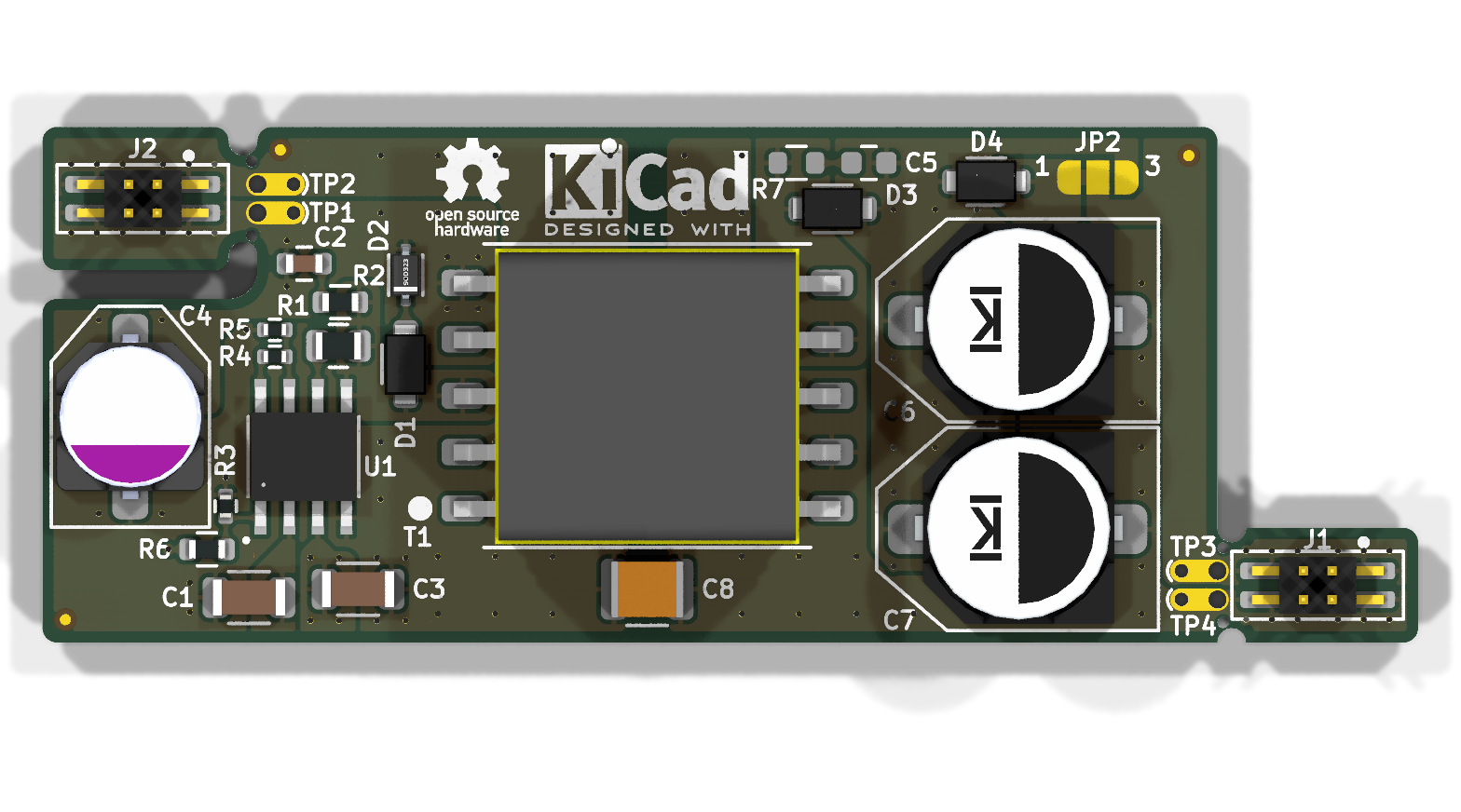 Top View of the PCB
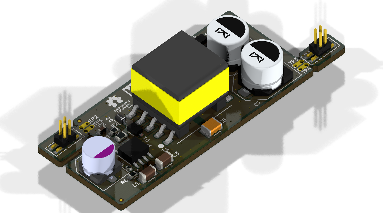 Side View of the PCB
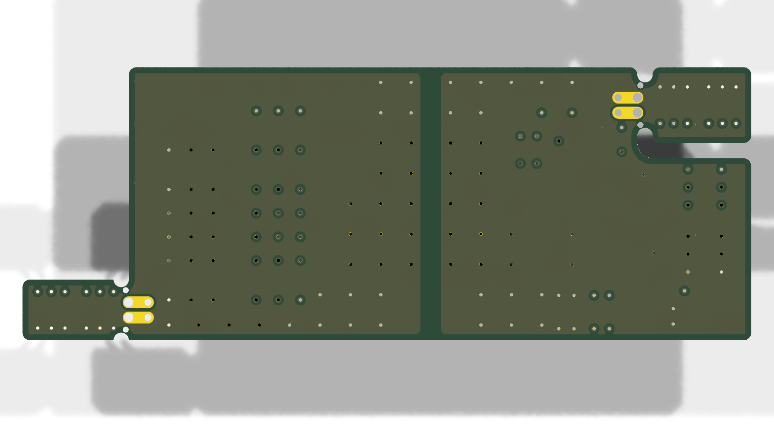 Bottom View of the PCB
This project is licensed under the MIT License - see the LICENSE file for details.
| Qty | Value | Footprint | References |
|---|---|---|---|
| 4 | TestPoint | test_point_footprints:TestPoint_THTPad_Castelated | TP1, TP2, TP3, TP4 |
| 3 | 100.0 V | diode_footprints:SOD123W | D1, D3, D4 |
| 3 | Fiducial | no_components_footprints:Fiducial_0.5mm_Mask1mm | FID1, FID2, FID3 |
| 2 | 100 kΩ | resistor_footprints:R_0402_1005Metric | R3, R4 |
| 2 | 100 Ω | resistor_footprints:R_0603_1608Metric | R2, R7 |
| 2 | 220 pF | capacitor_footprints:C_0603_1608Metric | C2, C5 |
| 2 | 33 µF | capacitor_footprints:C_034x0263_8_0x6_7Metric | C6, C7 |
| 2 | FW-02-03-G-D-085-155 | connector_footprints:FW-02-03-G-D-085-155 | J1, J2 |
| 2 | mouse-bite-midle-50mil-200mil | mouse_bite_footprints:mouse-bite-midle-50mil-200mil | MB1, MB2 |
| 1 | 1 MΩ | resistor_footprints:R_0603_1608Metric | R6 |
| 1 | 1 µF | capacitor_footprints:C_1206_3216Metric | C1 |
| 1 | 10 kΩ | resistor_footprints:R_0402_1005Metric | R5 |
| 1 | 10 µF | capacitor_footprints:C_1206_3216Metric | C3 |
| 1 | 22 µF | capacitor_footprints:C_023x0248_5_9x6_3Metric | C4 |
| 1 | 360 kΩ | resistor_footprints:R_0805_2012Metric | R1 |
| 1 | 4.7 nF | capacitor_footprints:C_1210_140_3225Metric | C8 |
| 1 | 51 V | diode_footprints:SOD323 | D2 |
| 1 | 750315836 | transformer_footprints:750315836 | T1 |
| 1 | LT8304IS8E-PBF | analog_devices_footprints:S_8E_ADI | U1 |
| 1 | SolderJumper_3_Open | solder_jumper_footprints:SolderJumper-3_P1.3mm_Bridged_1_2_RoundedPad1.0x1.5mm_NumberLabels | JP2 |
The 33 most common of 35 parts.
kquinsland/modular-rack-mount-power-system
Hardware, firmware, and host tooling for a modular mini-rack power system.


schlae/SynchroDriver
Various boards for driving synchros and other 400Hz devices


open-ephys/oe-acquisition-board-gen3
3rd Generation Open Ephys USB Acquisition Board


It measures 61 × 22.9 mm and has 4 copper layers, 1.6 mm thick.
35 parts, built around the PMEG10020AELRX, CRCW0603100RFKEAHP, CC0603JRNPO9BN221 and C1206R105K3RAC7800. The full list of its parts is on this page, with links to each part's symbol and footprint where PCBKit's library has them.
From the ionutms/Minimal_LT8304 repository on GitHub, at the commit this page was made from: the board is minimal_lt8304/minimal_lt8304.kicad_pcb and its schematic minimal_lt8304/minimal_lt8304.kicad_sch. PCBKit opens the board in the browser, with nothing to install.
Its repository publishes it under the MIT licence: you may reuse it on that licence's terms (keep the author's notice, and for a copyleft licence share your changes alike).