


2 layers99.7 × 78.7 mm
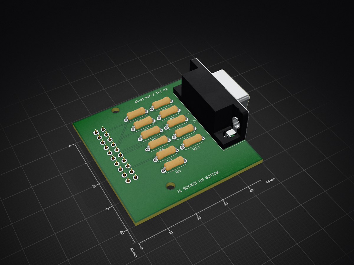
 iolo/a2ext
General purpose Apple II Extension Card using RP2350B
A2ext vga is an open-source printed circuit board by iolo, from the iolo/a2ext repository on GitHub. It is a 2-layer board of 45 × 45 mm with 15 parts on 29 nets, routed with 91 tracks and 0 vias.
Its parts include 11 resistors and 2 connectors.
Revision 0.3 uses A4 landscape with enlarged text: 1.524 mm pin names, wire labels and values, 1.27 mm pin numbers, and 1.778 mm references/notes. The revised layout preserves all electrical connections.
Passive DVI video daughterboard using an HDMI Type A connector and the PRD's 270 ohm series resistor network. Open the KiCad 10 project; symbols are local. The SH pin represents all four plated shell contacts. The physical PCB selects Kycon KDMIX-SL1-NS-WS-B15 for PCB-P2-THT. All 19 signal contacts and four shell tabs are through-hole. This upright right-angle port exits the right board edge; its approximately 16.4 mm body height and panel opening require a new fit check. The PCB-P1 Molex connector cannot fit this revision.
The 45 x 45 mm two-layer board uses axial 1/4 W DIN0207 270 ohm resistors
(7.62 mm formed pitch), a 5.0 mm pitch radial ceramic capacitor,
and a bottom-mounted 2x10 female socket at J1. H1/H2 are 2.7 mm spacer holes
aligned with the carrier. Resistor-to-HDMI pairs use a single layer per pair
without vias: D0/D1 on F.Cu and D2/clock on B.Cu. Output tuning keeps
intra-pair trace-length difference below 0.020 mm. Full routed lengths are in
validation/summary.json; the carrier and IDC-to-resistor segments are not
pair-length tuned. Controlled impedance and physical signal quality are unqualified.
See fabrication notes, Gerbers and drills,
top, bottom, and
assembly plots. DRC, ERC, and schematic parity
reports in validation/ have zero findings.
No SMD assembly or solder stencil is required. All four shell tabs require
plated slots; retain both drill files when ordering.
tmds-routing.json preserves the reviewed pair tracks during regeneration;
the placement generator locks them before routing the other nets.
| Lane | Positive GPIO / IDC | Negative GPIO / IDC | HDMI contacts |
|---|---|---|---|
| D0 | 36 / 4 | 37 / 5 | 7 / 9 |
| D1 | 38 / 6 | 39 / 7 | 4 / 6 |
| D2 | 40 / 8 | 41 / 9 | 1 / 3 |
| Clock | 42 / 10 | 43 / 11 | 10 / 12 |
Each conductor has a 270 ohm, 1% resistor. Shields, pin 17, shell, and both IDC ground contacts share GND. Pin 18 receives the carrier's fused +5V_DB supply; there is no additional series diode drop on this board. C1 decouples that rail. UART, RUN, 3.3 V power, GPIO35/44-47, DDC, HPD, CEC, and utility are unused.
The bundled libdvi program uses the lower GPIO for the positive conductor when
invert_diffpairs=false. Use PIO1 base 16 and 64-bit mask helpers. Its clock
generator uses the shared PWM slice for even/odd GPIO42/43. This is the
reference's resistor-driven signaling approach, not a claim of HDMI compliance.
Initially use direct carrier mating. No ribbon cable length is qualified. Validate a fixed 640x480 timing mode, pair polarity, eye/edge quality, connector +5 V, and lock on multiple monitors with a real board. No EDID negotiation or hotplug handling is implemented by this schematic. Carrier power comes from the slot input (or an off-host fixture at that input); USB is data only.
Validation so far: ERC and named-net export checks. Firmware and physical TMDS tests are pending. From the repository root:
python3 tools/schematics.py dvi
python3 tools/check_schematics.py a2ext-dvi
References: ref/A2DVI v5.x hardware and
ref/A2DVI-Firmware/libraries/libdvi/dvi_serialiser.{c,pio}.
| Qty | Value | Footprint | References |
|---|---|---|---|
| 3 | 1k 1% | A2Ext:R_Axial_7.62 | R2, R5, R8 |
| 3 | 2k 1% | A2Ext:R_Axial_7.62 | R1, R4, R7 |
| 3 | 500R 1% | A2Ext:R_Axial_7.62 | R3, R6, R9 |
| 2 | 47R | A2Ext:R_Axial_7.62 | R10, R11 |
| 2 | MountingHole_2.7mm_M2.5 | MountingHole_2.7mm_M2.5 | H1, H2 |
| 1 | Carrier IDC20 | A2Ext:Socket20 | J1 |
| 1 | DE-15HD female | A2Ext:VGA_DE15 | J2 |


google/mozc-devices
Circuit diagrams and firmware source code for Gboard DIY keyboards

hoglet67/RGBtoHDMI
Bare-metal Raspberry Pi project that provides pixel-perfect sampling of Retro Computer RGB/YUV video and conversion to HDMI

mntmn/amiga2000-gfxcard
MNT VA2000, an Open Source Amiga 2/3/4000 Graphics Card (Zorro II/III), written in Verilog

hackclub/OnBoard
💡 Join 1,000 teenagers and make your first PCB with a $100 grant!

kenp-io/not-for-airpods-repairs
The content of this repository is licensed under the WTFPL License. Please have a close look at the terms before using this material.

Luos-io/luos_engine
Open-source and real-time orchestrator for cyber-physical-systems, to easily design, test and deploy embedded applications and digital twins.

Chrismettal/EleLab_v2
Cheap DIY lab system for hobbyists and the tinkering folk

It measures 45 × 45 mm and has 2 copper layers, 1.6 mm thick.
15 parts. The full list of its parts is on this page, with links to each part's symbol and footprint where PCBKit's library has them.
From the iolo/a2ext repository on GitHub, at the commit this page was made from: the board is hw/a2ext-vga/a2ext-vga.kicad_pcb and its schematic hw/a2ext-carrier/a2ext-carrier.kicad_sch. PCBKit opens the board in the browser, with nothing to install.
Its repository states no licence, so its author keeps all rights: ask iolo before reusing the design.