
2 layers40.6 × 110 mm
Europi surface mount
Allen-Synthesis/EuroPi
EuroPi: A reprogrammable Eurorack module based on the Raspberry Pi Pico
92 parts584CC0-1.0

 inmbolmie/Save-a-Term10
Hardware for a PS/2 to 5251 and 3278 reverse keyboard adapter based on a TMK controller fork
Save a Term is an open-source printed circuit board by inmbolmie, from the inmbolmie/Save-a-Term repository on GitHub, published under the GPL-3.0 licence. It is a 2-layer board of 79 × 106 mm with 28 parts on 46 nets, routed with 443 tracks and 8 vias.
It is built around the L7805. Its parts include 10 resistors, 6 connectors, 3 capacitors, 2 switches and 1 IC. It belongs with the keyboards and input and interfaces and adapters boards and the AVR (ATmega, ATtiny) boards of this library.
Hardware for an IBM 5251 and 3278 reverse keyboard adapter to use a regular PS/2 keyboard with the original terminals. Based on my TMK controller fork (https://github.com/inmbolmie/ps2_to_4704_converter)
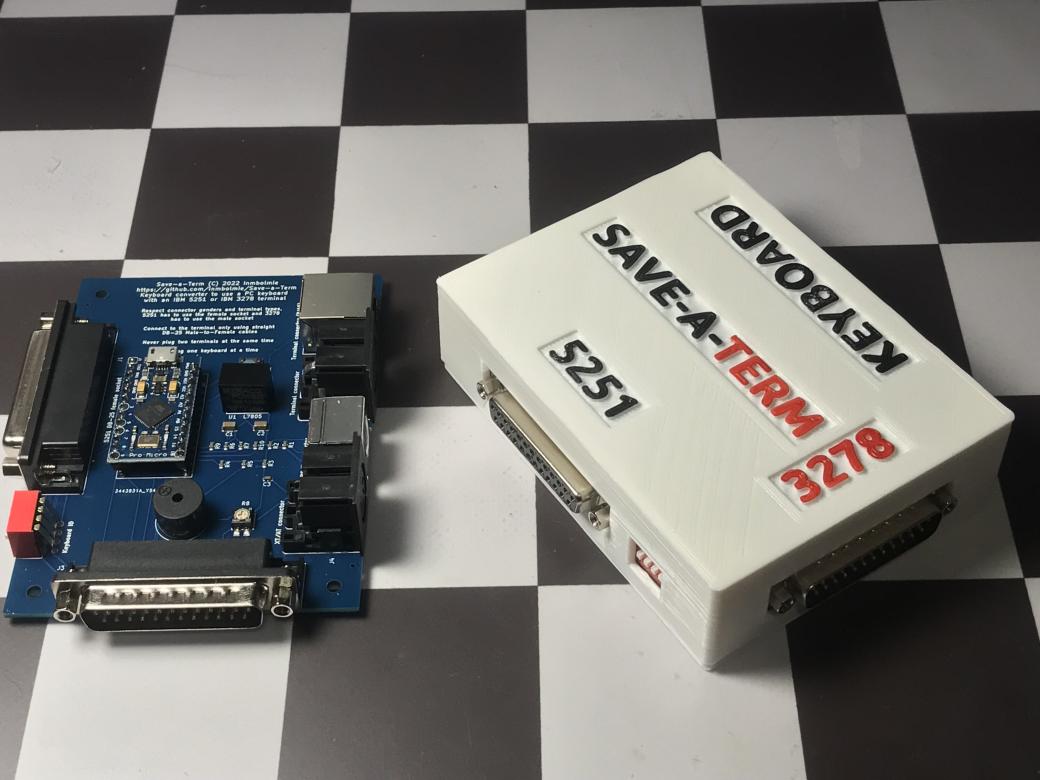
You got a pretty vintage 5251 or 3278 terminal but it lacks the original keyboard. The original keyboards are very expensive and sought-after items that can easily go for thousands of dollars. This adapter tries to solve that problem giving a way to use a cheap standard PS/2-like keyboard with the original terminals.
The adapter emulates the clicker functionality of the original keyboards using a buzzer to give audible feedback while typing.
The adapter will also auto-detect the terminal type (5251 or 3278) and use the correct scancode set and signal polarities for the connected terminal.
If you like it, want an adapter or PCB, or need any information not covered here you can drop me an email to the address: inmbolmie [AT] gmail [DOT] com
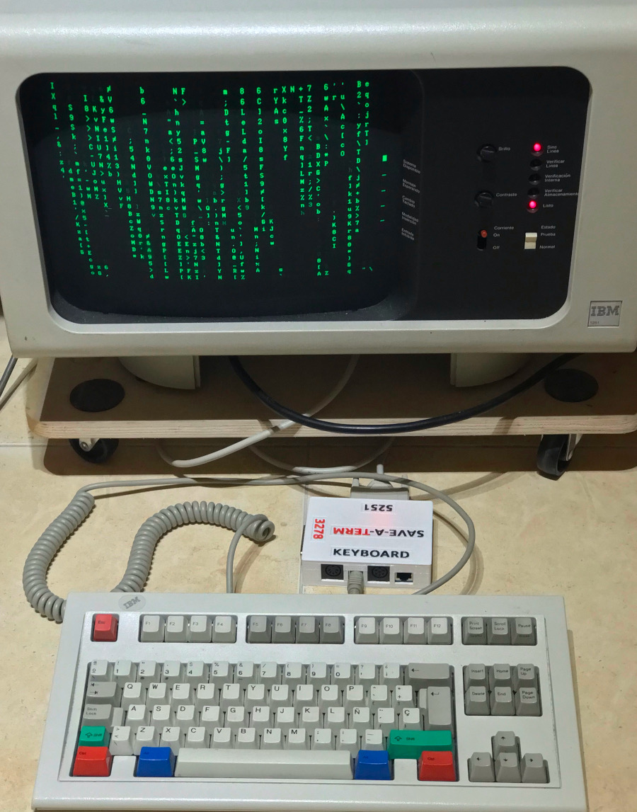
This converter is only compatible with original IBM 5251 and 3278 terminals.
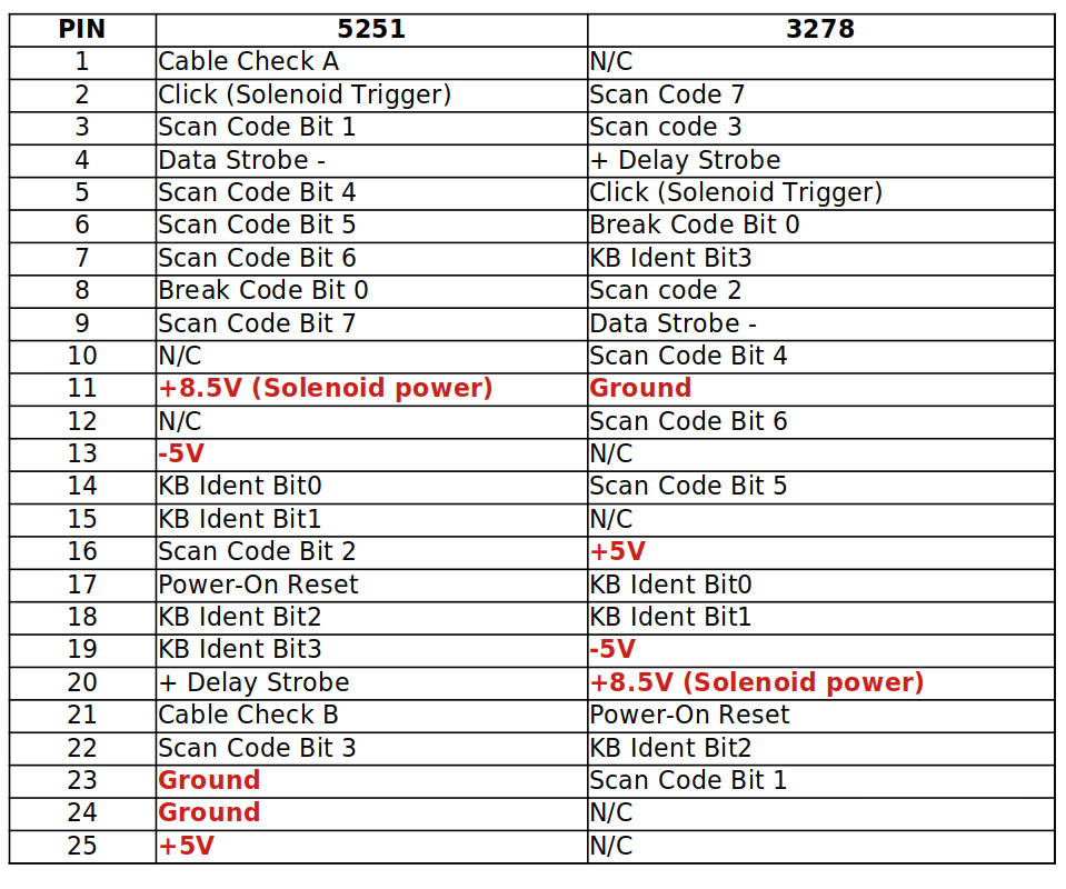
If not totally sure, check the voltages accross your terminal connector pins before plugging it to the adapter, here you have the expected 5251 and 3278 keyboard pinouts:
This adapter is not compatible with other similar IBM connectors like 3277, 5291 or Displaywriter, so do not try it with those.
This is not an adapter to plug an original 5251/3278 keyboard to a modern PC and won't ever work like that, so don't ask.
Pinouts are fully incompatible so a different connector is provided for each terminal type. Moreover, it is dangerous to connect the terminal to the wrong connector as pretty weird voltages will be misplaced accross the connector (+8.5V, +5V, -5V) so you can fry the converter and/or terminal doing that, so be warned.
This controller do not pretend to be universal in the sense some keyboards could be not compatible, but to provide a reasonable selection of cheap keyboards readily available. I have tested the converter using:
As said, it is not guaranteed that a particular keyboard will work, but there is a more than reasonable chance that any keyboard compatible with those metioned will work.
This converter is NOT compatible with USB keyboards. The pro-micro USB connector is provided only as way to update the controller's firmware.
The adapter will get power from the terminal connector, so no external power is needed.
For the connection to the terminal you have to use a male-to-female straight DB-25 cable
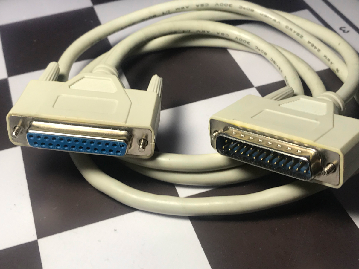
To use the adapter you simply have to plug ONE keyboard to one of the 4 available ports (RJ45, DIN5-240º, DIN5-180º, PS/2) and the terminal to the right DB-25 connector (female for 5251 and male for 3278). The terminal type and connector gender is also clearly marked on the PCB silkscreen. Check that your cable is really straight, pin 1 goes to pin 1, pin 2 goes to pin 2, etc. It is of the utmost importance not to mix genders or plug the terminal to the wrong connector, as pretty high voltages are involved on the connectors (+8.5V, +5V. -5V) and the pinouts are incompatible. If you get it wrong you will damage the adapted and/or terminal. You cannot get it wrong if you stick to only using a male-to-female straight DB25 cable, as there is no way of plugging it on a wrong configuration.
The adapter will auto-detect the terminal type (5251 or 3278) and use the correct scancode set and signal polarities for the connected terminal.
The buzzer volume can be adjusted using the on-board potentiometer. On the spririt of the original keyboards, the buzzer can be totally silenced only from the terminal (like the clicker on the original keyboards).
The included DIP switches allow to configure a 4-bit keyboard-id for the terminal. The keyboard-id is exclusively used by the terminal and do not modify the adapter operation.
The layouts are designed to replicate the original keyboard functionality. They are not configurable.
This is the recommended layout for 5251, as it is exactly the same as the original keyboard
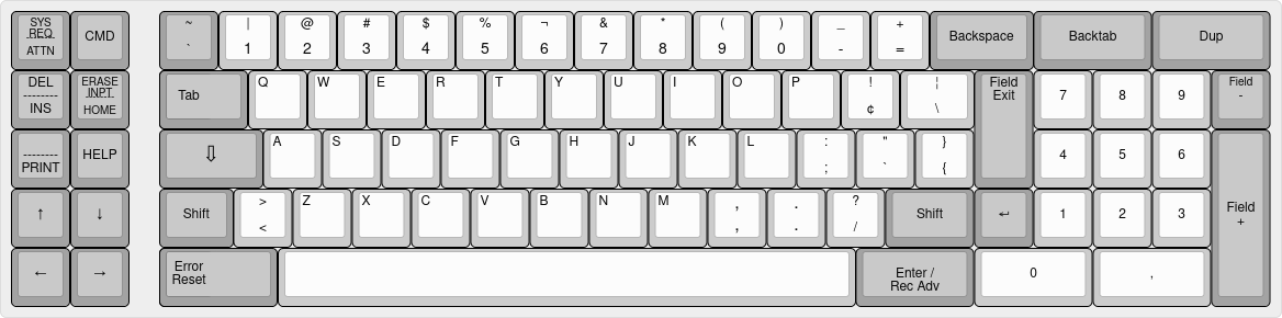
Offers the same functionality as the original keyboard, placing keys on similar positions.
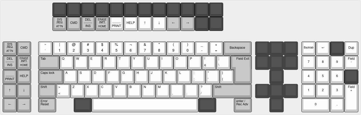
This is the recommended layout for 3278, offers extra fuctionality and layout loosely based on 122-key 3270-compatible terminals
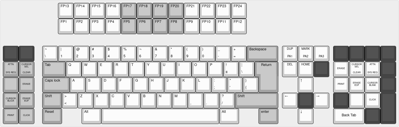
Do not use it as some keys will be on weird places, offered only for compatibility reasons.
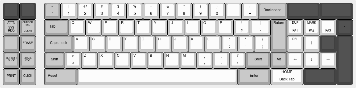
The design is based on the pro-micro version of TMK adding parallel protocol compatibility.
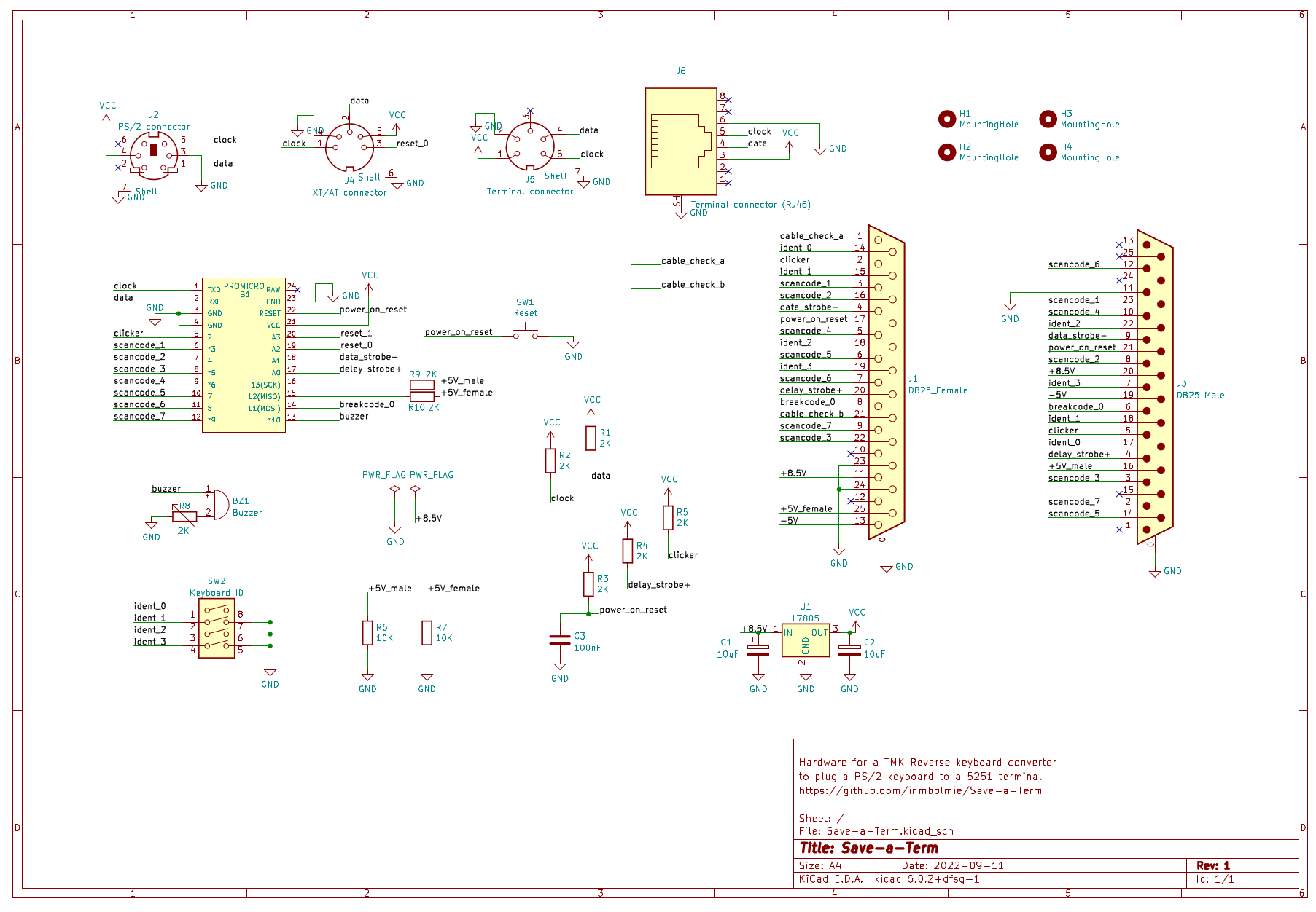
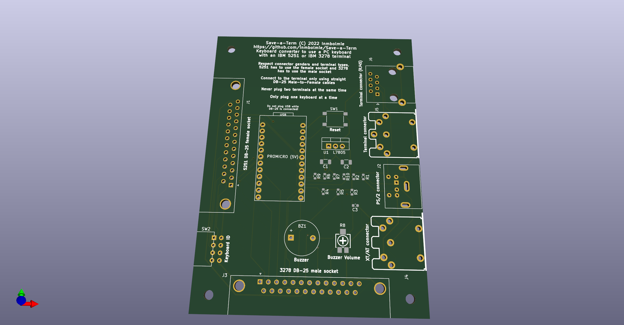
I provide the STL files for a 3D-printed case (case and lid). The case is assembled using 4 M3x10mm tapered head screws.
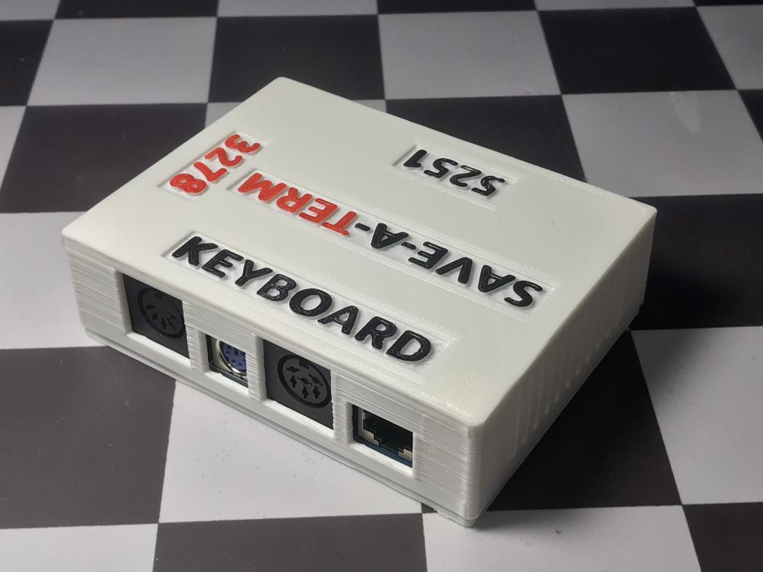
You can order the PCB's directly from JLCPCB using the provided gerber, bom, and cpl files on the pcb directory. You can easily generate files for other fabricators from the Kicad project files.
For the assembly be sure you get the correct gender for DB-25 connectors respecting what is indicated on the silkscreen legends.
You have to use a 5V-16Mhz Arduino pro-micro genuine or compatible microcontroller.
The 7805 regulator can be a regular 7805 or (better) a DC-to-DC pin compatible replacement like a Traco TSR 1-2450E. A 7805 is used to power the board from the 8.5V rail instead of using the +5V rail directly because I found the latter unstable and sometimes providing insufficient voltage to power the controller reliably.
You have to use my fork of TMK https://github.com/inmbolmie/ps2_to_4704_converter
git clone https://github.com/inmbolmie/ps2_to_4704_converter.git
Go to the converter/ibmpc_ibm5251 directory and generate the firmware file executing:
cd ps2_to_4704_converter/converter/ibmpc_ibm5251/
make -f Makefile.atmega32u4
To program the controller, connect it to an USB port on your computer, making sure no terminal is connected to the adapter in case the controller is already soldered on the board. Then push the RESET button on the board and execute on your computer:
avrdude -p m32U4 -P /dev/ttyACM0 -c avr109 -U flash:w:ibmpc_ibm5251_atmega32u4.hex
Where ibmpc_ibm5251_atmega32u4.hex is the name of the generated firmware file.
The device name ttyACM0 could have to be changed to whatever device name your computer assigns to your controller.
Do not plug the USB port while a terminal is connected to the adapter
You will need to have the tools needed to build TMK, follow the general instrucions from the TMK code to configure your build environment.
After successful programming you will get output like this:
Connecting to programmer: .
Found programmer: Id = "CATERIN"; type = S
    Software Version = 1.0; No Hardware Version given.
Programmer supports auto addr increment.
Programmer supports buffered memory access with buffersize=128 bytes.

Programmer supports the following devices:
    Device code: 0x44

avrdude: AVR device initialized and ready to accept instructions

Reading | ################################################## | 100% 0.00s

avrdude: Device signature = 0x1e9587 (probably m32u4)
avrdude: NOTE: "flash" memory has been specified, an erase cycle will be performed
         To disable this feature, specify the -D option.
avrdude: erasing chip
avrdude: reading input file "ibmpc_ibm5251_atmega32u4.hex"
avrdude: input file ibmpc_ibm5251_atmega32u4.hex auto detected as Intel Hex
avrdude: writing flash (27136 bytes):

Writing | ################################################## | 100% 1.69s

avrdude: 27136 bytes of flash writtenNow your controller is ready to be used.
| Qty | Value | Footprint | References |
|---|---|---|---|
| 7 | 2K | Resistor_SMD:R_0603_1608Metric | R1, R2, R3, R4, R5, R9, R10 |
| 4 | MountingHole | MountingHole:MountingHole_3.2mm_M3 | H1, H2, H3, H4 |
| 2 | 10K | Resistor_SMD:R_0603_1608Metric | R6, R7 |
| 2 | 10uF | Capacitor_SMD:C_1206_3216Metric | C1, C2 |
| 1 | 100nF | Capacitor_SMD:C_0603_1608Metric | C3 |
| 1 | 500 | mis_partes:RES-ADJ-SMD_G43BT | R8 |
| 1 | Buzzer | Buzzer_Beeper:Buzzer_12x9.5RM7.6 | BZ1 |
| 1 | DB25_Female | Connector_Dsub:DSUB-25_Female_Horizontal_P2.77x2.84mm_EdgePinOffset7.70mm_Housed_MountingHolesOffset9.12mm | J1 |
| 1 | DB25_Male | Connector_Dsub:DSUB-25_Male_Horizontal_P2.77x2.84mm_EdgePinOffset7.70mm_Housed_MountingHolesOffset9.12mm | J3 |
| 1 | Keyboard ID | mis_partes:Dip SW lateral 4 | SW2 |
| 1 | L7805 | Package_TO_SOT_THT:TO-220-3_Vertical | U1 |
| 1 | PROMICRO | promicro:SPARKFUN_PRO_MICRO | B1 |
| 1 | PS/2 connector | ps2:Connector_Mini-DIN_Female_6Pin_2rows | J2 |
| 1 | Reset | Button_Switch_SMD:SW_Push_1P1T_NO_6x6mm_H9.5mm | SW1 |
| 1 | Terminal connector | mis_partes:DIN-6 | J5 |
| 1 | Terminal connector (RJ45) | Connector_RJ:RJ45_Ninigi_GE | J6 |
| 1 | XT/AT connector | mis_partes:DIN-5 | J4 |
Allen-Synthesis/EuroPi
EuroPi: A reprogrammable Eurorack module based on the Raspberry Pi Pico

peterheinrich/InternetOverSpaghetti
Transmitting IP packages over a pair of spaghetti thus demonstrating how media independent IP really is.


Tircown/ERCF-easy-brd
More informations on how to reset for flashing:\ https://wiki.seeedstudio.com/Seeeduino-XIAO/#enter-bootloader-mode

matthewcieplak/super-sixteen
Code and schematics for the Super Sixteen Eurorack sequencer

NikodemBartnik/Mini-Mars-Rover
Educational robotic platform made to look like a mini mars rover

starlightk7/OpenSFC
OSHW Reproduction Parts related to the Super Famicom / Super Nintendo game console

Redherring32/OpenTendo-TopLoader
An Open Source HardWare (OSHW) recreation of the 1993 toploading NES motherboard (Also known as NES-101)
It measures 79 × 106 mm and has 2 copper layers, 1.6 mm thick.
28 parts, built around the L7805. The full list of its parts is on this page, with links to each part's symbol and footprint where PCBKit's library has them.
From the inmbolmie/Save-a-Term repository on GitHub, at the commit this page was made from: the board is Kicad/Save-a-Term.kicad_pcb and its schematic Kicad/Save-a-Term.kicad_sch. PCBKit opens the board in the browser, with nothing to install.
Its repository publishes it under the GPL-3.0 licence: you may reuse it on that licence's terms (keep the author's notice, and for a copyleft licence share your changes alike).