

2 layers370.8 × 298.5 mm
8 Bit Computer
The-Invent0r/8-bit-Computer-PCB
These are the KiCAD files for my 8-Bit Computer.
323 parts142

 inmbolmie/FloppyBird2
Disk interface to adapt an PC floppy drive to an IBM 31SD/51TD controller
FloppyBird is an open-source printed circuit board by inmbolmie, from the inmbolmie/FloppyBird repository on GitHub, published under the GPL-3.0 licence. It is a 2-layer board of 88.9 × 59.7 mm with 33 parts on 69 nets, routed with 645 tracks and 34 vias.
It is built around the 74LS04PC, 74LS32SC and 74LS86. Its parts include 8 capacitors, 7 resistors, 6 ICs, 4 switches and 3 connectors. It belongs with the interfaces and adapters boards and the AVR (ATmega, ATtiny) boards of this library.
Disk interface to adapt a Gotek floppy emulator to an IBM 31SD/51TD controller

This adapter will allow to connect a regular PC Floppy or Gotek emulator to an IBM 8" host like those big-iron machines that use the IBM 31SD and 51TD diskette drives.

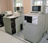
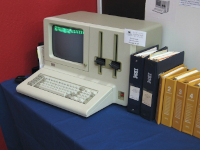
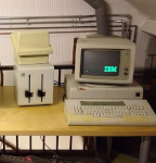
The target device is a Gotek emulator running FlashFloppy, but in theory it should be possible to use a real 5,25 1.2MB floppy drive, as they have 80 tracks (only 77 are needed to emulate an IBM Diskette) and they rotate at 360 RPM like the regular IBM 8" diskettes.
Note that a newer Gotek with the AT32F435 controller is required as older devices with the STM32F105 and AT32F415 controllers are not powerful enough to emulate IBM diskettes reliably. The adapter has only been tested with the FlashFloppy firmware and HFE disk images generated with the HxC software.
The current version is capable of reading, writing and formatting Diskette 1 (SSSD), Diskette 2 (DSSD) and Diskette 2D (DSDD) types on a AT32F435 Gotek.
If you like it or want to make your unit drop me a message to inmbolmie [AT] gmail.com
Here it is the adapter installed alongside a custom Gotek in my IBM 4701-2 controller, installed on the place where the IBM 51TD Diskette drive uses to be:
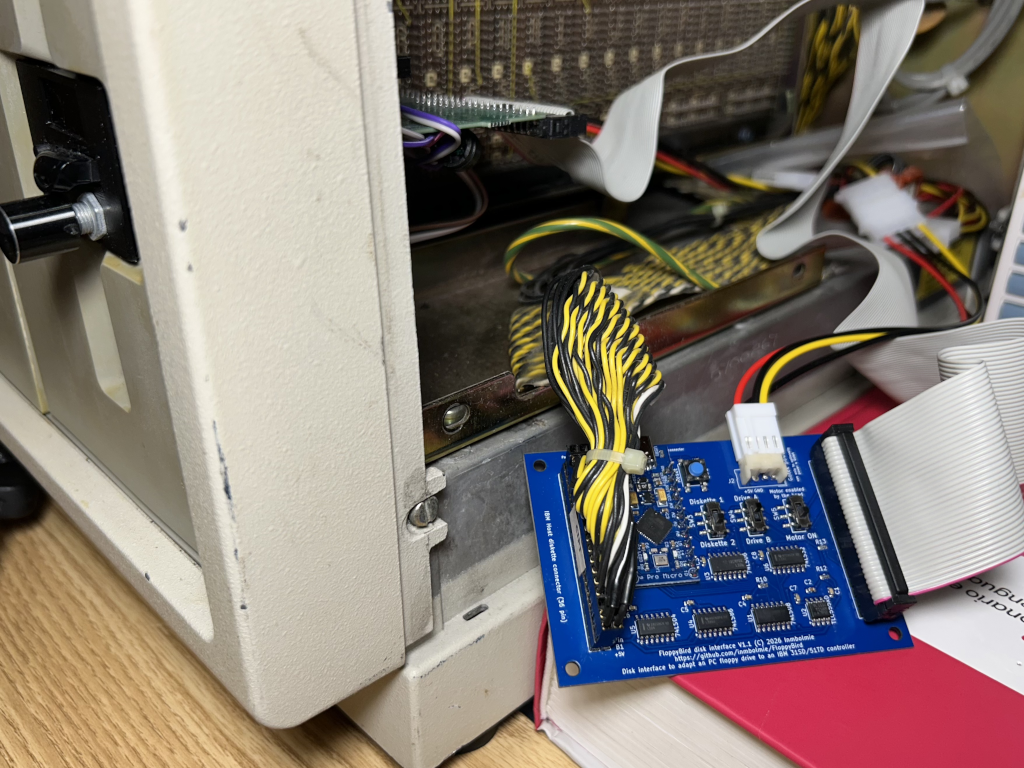
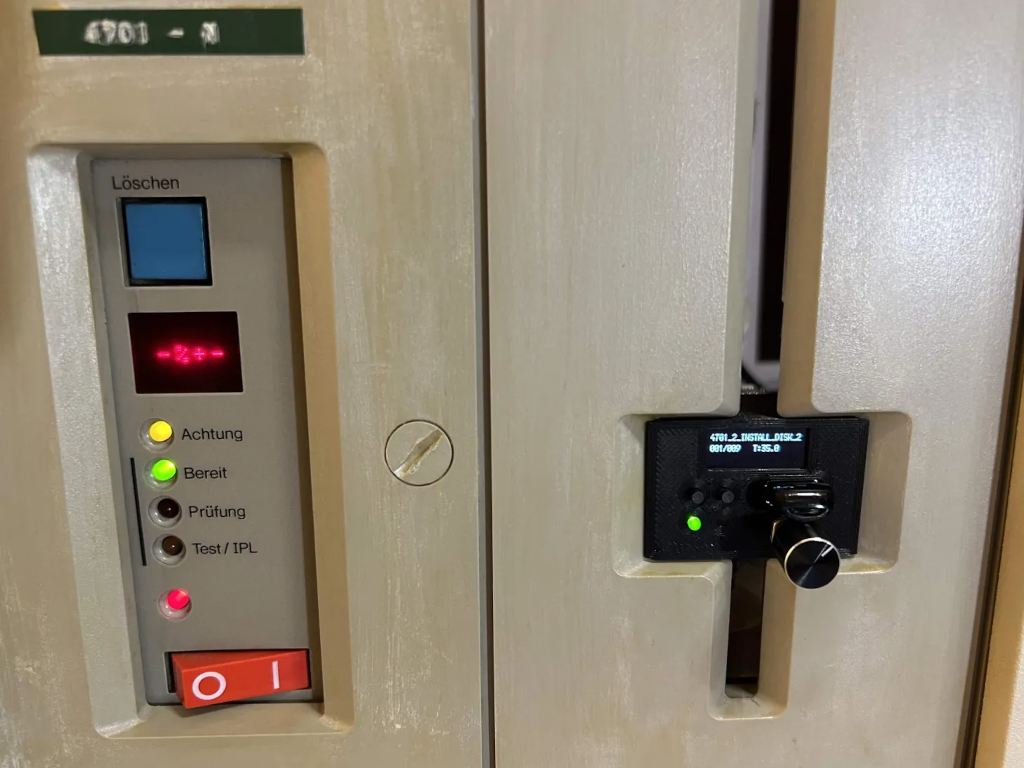
Note that this project is still work in progress, it only has been tested on my own hardware.
Video showing my IBM 4701-2 controller formating a 2D Diskette on a HFE disk image with FloppyBird and a AT32F435 Gotek: https://www.youtube.com/watch?v=8-GUEEburHQ
interface = ibmpc
host = unspecified
max-cyl = 77
side-select-glitch-filter = 0
track-change = realtime
write-drain = realtime
index-suppression = no
head-settle-ms = 10
motor-delay = ignore
chgrst = step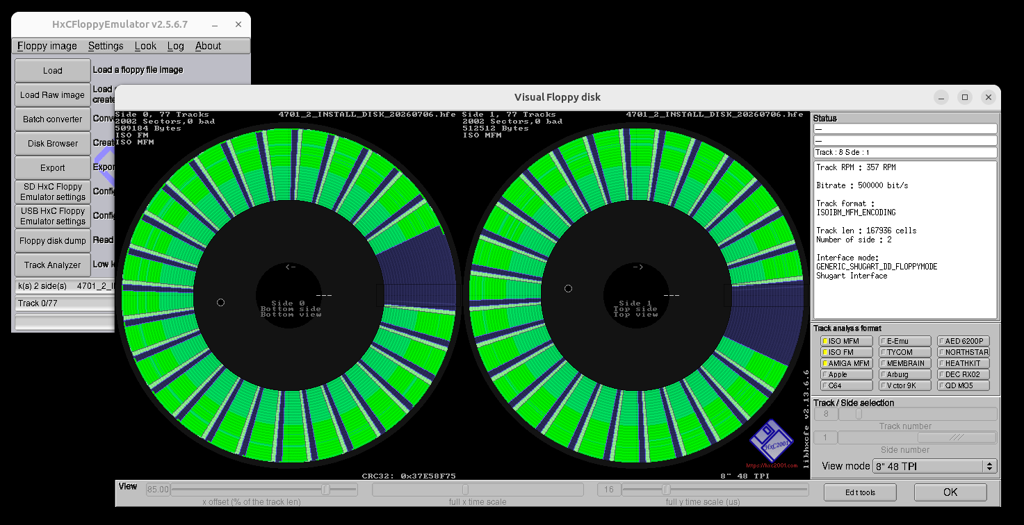
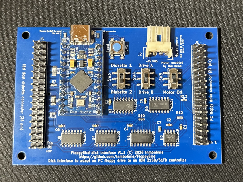
Board installed in the system, IBM diskette interface connector on the left (pin B1 is facing to the bottom), Gotek floppy cable on the right (pin 1 is also facing to the bottom), floppy power connector to power the Gotek on the top (+5V pin facing to the left).
Now your floppy emulator is ready to be used.
Note that the adapter will honor the PC floppy disk protection signal, so if the disk is write protected it will prevent it to be written by the IBM host. The IBM host does not have any provision to manage "write protected" diskettes though, so in that case it will generate an error if it tries to write to the diskette.
Apart from HFE images, IMG disk images also work partially. They have the problem that if a sector is marked as "control field" there is no way to store the correct Address Mark on a IMG disk image, so the Gotek will fail to write that data properly and will result in a write error.
The adapter board providing supply to a Gotek AT32F435 drags around 350 milliamps from the IBM host through the +5V rail.
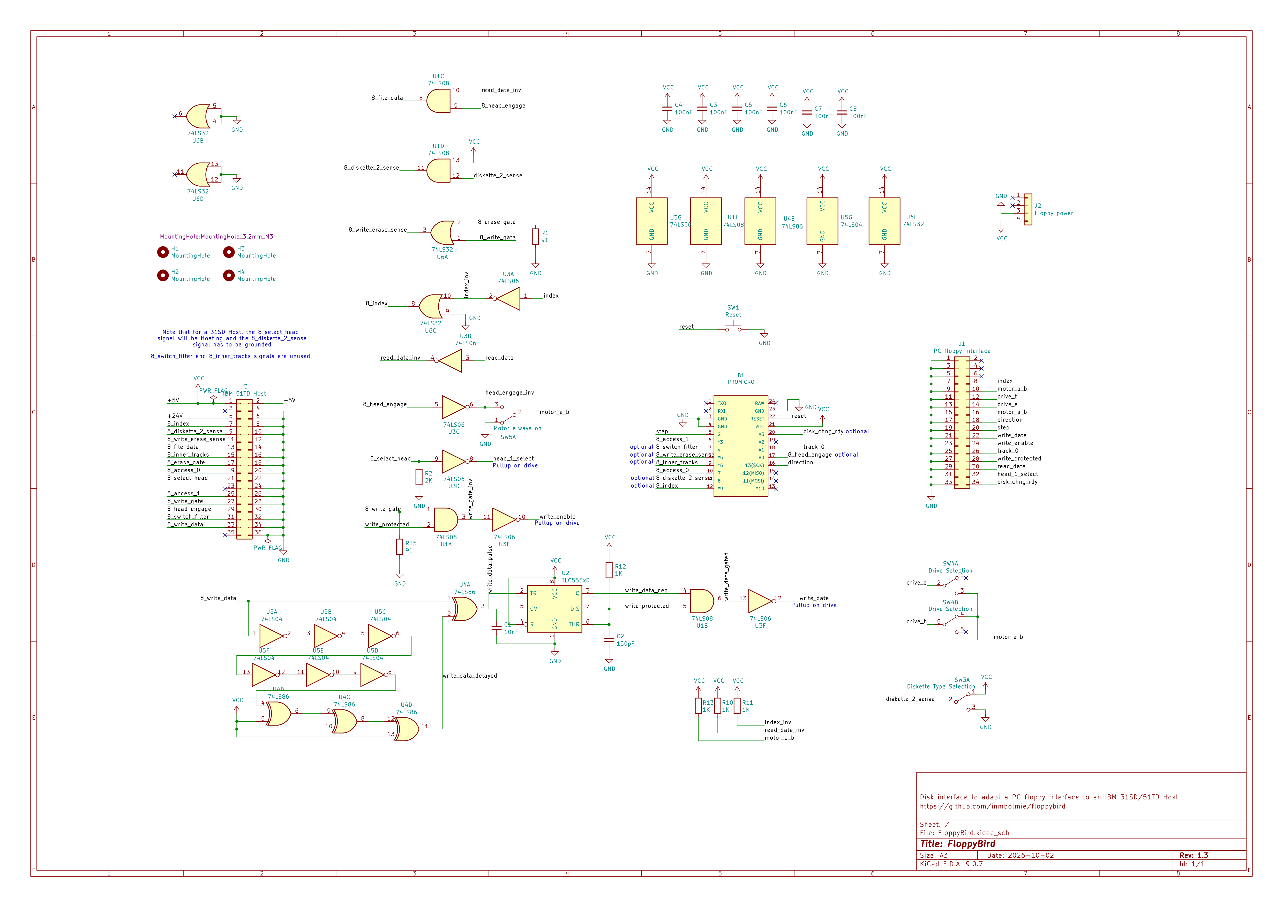
Schematics for the 1.3 version.
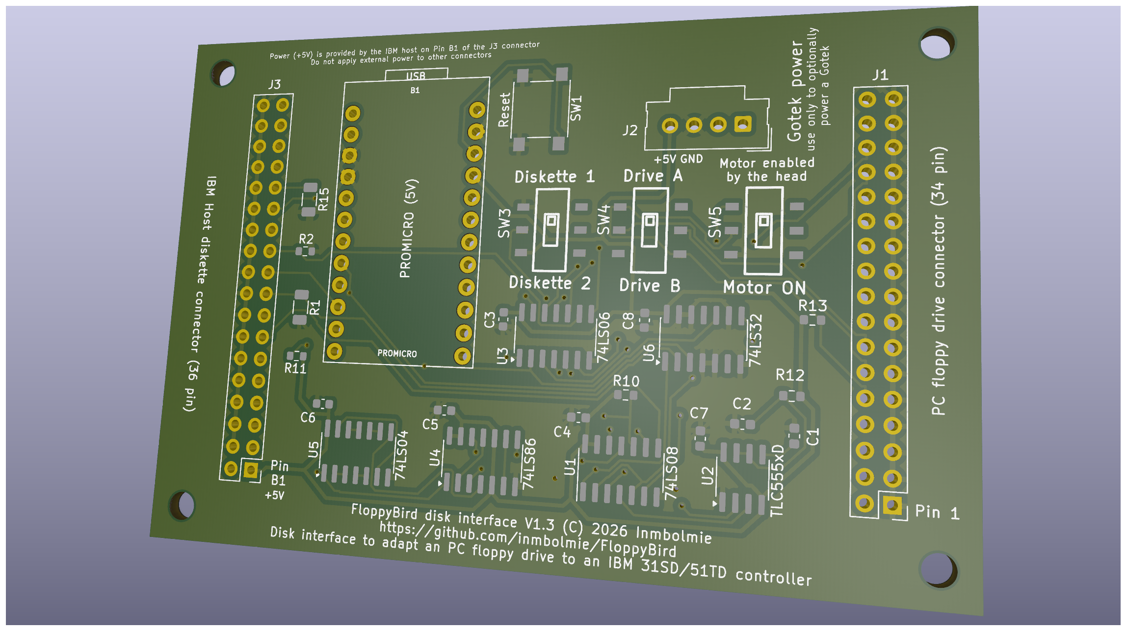
Sample image of the PCB from Kicad.
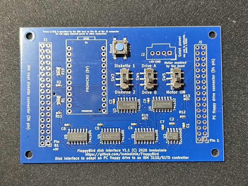
Real board partially assembled (v1.1) as it comes from the PCB fabricator. It came with all the SMT components already installed:
Board totally assembled with the Pro-micro, pin headers and floppy power connector installed. Note that pin B2 (key pin) is missing from the IBM host connector, and pin 3 (key pin) is also missing from the PC Floppy connector:
You can get the Arduino source code for the ProMicro in the FloppyBird directory. You can compile it and program on the ProMicro using the regular Arduino IDE.
You can get the current project files in the KiCad directory.
You can order directly your boards from a PCB fabricator, just the board or partially assembled with the files on the pcb directory (gerber, bom and component placement files in jlcpcb format).
In any case you will have to add:
Before ordering anything note that this project is still work in progress, it only has been tested on my own hardware.
These are the main points that need to be carried out for conversion:
The PC floppy signals are open collector low-level active, while the IBM signals are push-pull high-active. The 74 series chips provide most of the conversion.
The PC floppy adresses tracks by a direction and step signal, and gets a track_0 signal when the head is placed at such track. The IBM interface lacks a track_0 signal and you control direcly the stepper motor signals access_0 and access_1. The ProMicro initializes the head position at track 0 at startup. From there it gets track of where the head is actually positioned and translates the required signals on both sides.
The read_data_signal is gated by the head_engage signal. It is essentially the same signal for both systems but with reversed polarity.
The PC floppy write data signal generates a full pulse (falling and rising edge) for each magnetic flux transition that needs to be recorded on the disk surface, while in the IBM interface the write_data signal records a magnetic flux transition for each signal level change (rising or falling edge). The conversion is made via a homemade edge detector (74LS04 + 74LS86) followed by a pulse generator (TLC555). The TLC555 is used over other 555 variants due to its superior speed and stability.
The write_gate and erase_gate signals are terminated with 90 ohm resistors like in the original IBM drives to prevent phantom writes. Those signals control the write_data signal going to the PC floppy and they are feed back to the IBM controller on the write_erase_sense signal
Contrary to the PC Floppy, an 8" drive is permanently turning, so the PC drive should be by default always rotating to emulate this and generate the index signal continously. Optionally a swith is provided to make the drive rotation conditional to the head_engage signal.
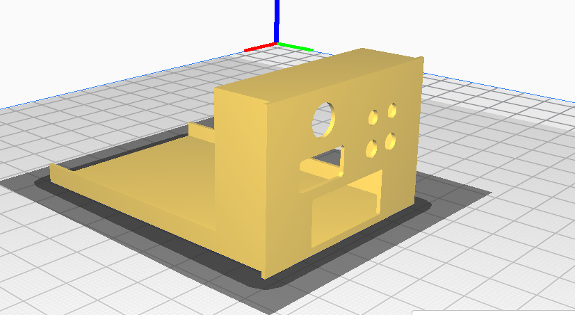
I provide the STL file to create the case shown in the pictures and video in the case directory. It allows to install a Gotek with an oled display and rotary switch in the slot designed for the IBM 51TD drive on my 4701 controller.
Note that the case is a very simple design, it is a tight fit, it is quite difficult to install, may not be adequate for other systems and also has no provision to secure it using screws or other mounting methods, it stays in place just by itself.
| Qty | Value | Footprint | References |
|---|---|---|---|
| 6 | 100nF | Capacitor_SMD:C_0603_1608Metric | C3, C4, C5, C6, C7, C8 |
| 4 | 1K | Resistor_SMD:R_0603_1608Metric | R10, R11, R12, R13 |
| 4 | MountingHole | MountingHole:MountingHole_3.2mm_M3 | H1, H2, H3, H4 |
| 2 | 91 | Resistor_SMD:R_1206_3216Metric | R1, R15 |
| 1 | 10nF | Capacitor_SMD:C_0603_1608Metric | C1 |
| 1 | 150pF | Capacitor_SMD:C_0603_1608Metric | C2 |
| 1 | 2K | Resistor_SMD:R_0603_1608Metric | R2 |
| 1 | 74LS04 | Package_SO:SO-14_3.9x8.65mm_P1.27mm | U5 |
| 1 | 74LS06 | Package_SO:SO-14_3.9x8.65mm_P1.27mm | U3 |
| 1 | 74LS08 | Package_SO:SO-14_3.9x8.65mm_P1.27mm | U1 |
| 1 | 74LS32 | Package_SO:SO-14_3.9x8.65mm_P1.27mm | U6 |
| 1 | 74LS86 | Package_SO:SO-14_3.9x8.65mm_P1.27mm | U4 |
| 1 | Diskette Type Selection | dpdt_2:SW-SMD_SS-3235S-L3.00 | SW3 |
| 1 | Drive Selection | dpdt_2:SW-SMD_SS-3235S-L3.00 | SW4 |
| 1 | Floppy power | Connector_Molex:Molex_SL_171971-0004_1x04_P2.54mm_Vertical | J2 |
| 1 | IBM 51TD Host | Connector_PinHeader_2.54mm:PinHeader_2x18_P2.54mm_Vertical | J3 |
| 1 | Motor always on | dpdt_2:SW-SMD_SS-3235S-L3.00 | SW5 |
| 1 | PC floppy interface | Connector_PinHeader_2.54mm:PinHeader_2x17_P2.54mm_Vertical | J1 |
| 1 | PROMICRO | promicro:SPARKFUN_PRO_MICRO | B1 |
| 1 | Reset | Button_Switch_SMD:SW_Push_1P1T_NO_6x6mm_H9.5mm | SW1 |
| 1 | TLC555xD | Package_SO:SOIC-8_3.9x4.9mm_P1.27mm | U2 |
It measures 88.9 × 59.7 mm and has 2 copper layers, 1.6 mm thick.
33 parts, built around the 74LS04PC, 74LS32SC and 74LS86. The full list of its parts is on this page, with links to each part's symbol and footprint where PCBKit's library has them.
From the inmbolmie/FloppyBird repository on GitHub, at the commit this page was made from: the board is KiCad/FloppyBird.kicad_pcb and its schematic KiCad/FloppyBird.kicad_sch. PCBKit opens the board in the browser, with nothing to install.
Its repository publishes it under the GPL-3.0 licence: you may reuse it on that licence's terms (keep the author's notice, and for a copyleft licence share your changes alike).
The-Invent0r/8-bit-Computer-PCB
These are the KiCAD files for my 8-Bit Computer.

hkzlab/CGA_Redux
The Color Graphics Adapter Redux board is a more or less faithful clone of the original IBM CGA, based on the original schematics


fortinsylvain/MyCpu
Home brew CPU Hardware with 1-bit ALU implementation using 74LSxx, a micro-code and assembler coded in C#.

clemarfolly/Microdigital-TK2000
Reprodução da PCB do TK-2000 da Microdigital, clone do Micro-Professor MPF-II


misterblack1/zenith_zt1
Information gathered on the Zenith ZT-1 / ZT-10 / ZT-11 and ZTX/ZT-x-A variants