4 layers124.7 × 64.3 mm
RP2040 SOS band
abhinav937/RP2040_SOS_band
PCB design files for RP2040 based SmartWatch. It features an accelerometer, a GPS module and a cellular module.
107 parts3
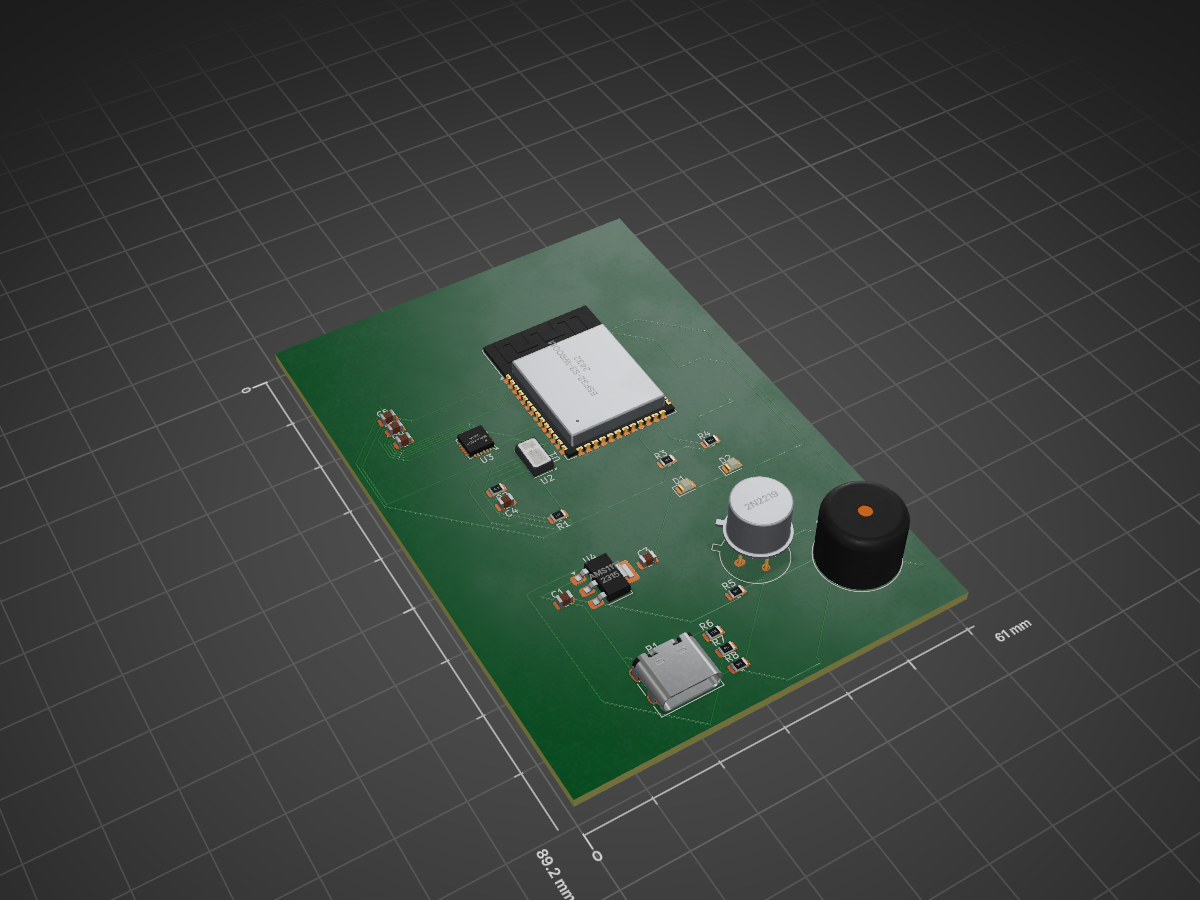
 include-stdioH/TriVision-Smart-Driver-Monitoring-Board
ESP32-S3 based Smart Driver Monitoring Sensor Board designed in KiCad.
TRIVISION sensor board is an open-source printed circuit board by include-stdioH, from the include-stdioH/TriVision-Smart-Driver-Monitoring-Board repository on GitHub. It is a 2-layer board of 61 × 89.2 mm with 23 parts on 66 nets, routed with 260 tracks and 0 vias.
It is built around the ESP32-S3-WROOM-1-N8, MAX30102 and AMS1117, with the MPU-6050 among its other parts. Its parts include 8 resistors, 6 capacitors, 4 ICs, 2 diodes and 1 transistor. It belongs with the sensors and measurement boards and the ESP32 boards of this library.


ESP32-S3 based Smart Driver Monitoring Sensor Board designed in KiCad.
TriVision is a custom-designed ESP32-S3-based sensor board developed for intelligent driver monitoring and vehicle safety applications. The board integrates biometric and motion sensing capabilities to detect driver fatigue, drowsiness, distraction, and abnormal driving conditions.
This project was designed using KiCad and includes complete schematic design, PCB layout, component placement, routing, and 3D visualization.
| Component | Function |
|---|---|
| ESP32-S3-WROOM-1 | Main microcontroller |
| MAX30102 | Heart-rate and SpO₂ sensor |
| MPU6050 | Accelerometer and gyroscope |
| AMS1117-3.3 | Voltage regulator |
| USB Type-C | Power input |
| Buzzer | Driver warning alerts |
| LEDs | System status indication |
USB-C Power Input → AMS1117 → 3.3V Rail
ESP32-S3 ↔ MAX30102 (I²C)
ESP32-S3 ↔ MPU6050 (I²C)
ESP32-S3 → Buzzer
ESP32-S3 → Status LEDs
Anushri Logesh
Electronics and Communication Engineering
Embedded Systems & AI Enthusiast
| Qty | Value | Footprint | References |
|---|---|---|---|
| 4 | 100n | Capacitor_SMD:C_0805_2012Metric | C4, C5, C6, C9 |
| 2 | 10u | Capacitor_SMD:C_0805_2012Metric | C1, C3 |
| 2 | 330 | Resistor_SMD:R_0805_2012Metric | R3, R4 |
| 2 | 4.7K | Resistor_SMD:R_0805_2012Metric | R1, R2 |
| 2 | 5.1K | Resistor_SMD:R_0805_2012Metric | R6, R7 |
| 1 | 10K | Resistor_SMD:R_0805_2012Metric | R8 |
| 1 | 1K | Resistor_SMD:R_0805_2012Metric | R5 |
| 1 | 2N2219 | Package_TO_SOT_THT:TO-39-3 | Q1 |
| 1 | AMS1117 | Package_TO_SOT_SMD:SOT-223-3_TabPin2 | U4 |
| 1 | Buzzer | Buzzer_Beeper:Buzzer_12x9.5RM7.6 | BZ1 |
| 1 | ESP32-S3-WROOM-1 | RF_Module:ESP32-S3-WROOM-1 | U1 |
| 1 | GREEN | LED_SMD:LED_0805_2012Metric | D1 |
| 1 | MAX30102 | OptoDevice:Maxim_OLGA-14_3.3x5.6mm_P0.8mm | U2 |
| 1 | MPU-6050 | Sensor_Motion:InvenSense_QFN-24_4x4mm_P0.5mm | U3 |
| 1 | RED | LED_SMD:LED_0805_2012Metric | D2 |
| 1 | USB_C_Plug_USB2.0 | Connector_USB:USB_C_Receptacle_HRO_TYPE-C-31-M-12 | P1 |
abhinav937/RP2040_SOS_band
PCB design files for RP2040 based SmartWatch. It features an accelerometer, a GPS module and a cellular module.


amajha2166/ESP32-Based_OrthoStatic-Hypotension_Monitoring_Device
An ESP32-based wearable monitoring prototype integrating MAX30102 heart-rate and SpO₂ sensing, MPU6050 posture detection, Qt GUI visualization, Wi-Fi communication, event-based alerts, and KiCad hardware design.


impatrq/healthband
La incorporación de un Bot de Telegram 💬 permitirá recibir alertas, consultar el estado de salud e información general.


NITHYAR2005/PCB-BOARD-DESIGN-FOR-IOT-ENABLED-WEARABLE-HEALTH-MONITOR
It measures 61 × 89.2 mm and has 2 copper layers, 1.6 mm thick.
23 parts, built around the ESP32-S3-WROOM-1-N8, MAX30102, AMS1117 and MPU-6050. The full list of its parts is on this page, with links to each part's symbol and footprint where PCBKit's library has them.
From the include-stdioH/TriVision-Smart-Driver-Monitoring-Board repository on GitHub, at the commit this page was made from: the board is TRIVISION-sensor board.kicad_pcb and its schematic TRIVISION-sensor board.kicad_sch. PCBKit opens the board in the browser, with nothing to install.
Its repository states no licence, so its author keeps all rights: ask include-stdioH before reusing the design.