2 layers96.5 × 55 mm
Vera full audiojack
ifilot/open-vera-module
VERA (Versatile Embedded Retro Adapter) is a self-contained FPGA video and audio module for retro-computing projects.
105 partsMIT
 ifilot/open-vera-module
VERA (Versatile Embedded Retro Adapter) is a self-contained FPGA video and audio module for retro-computing projects.
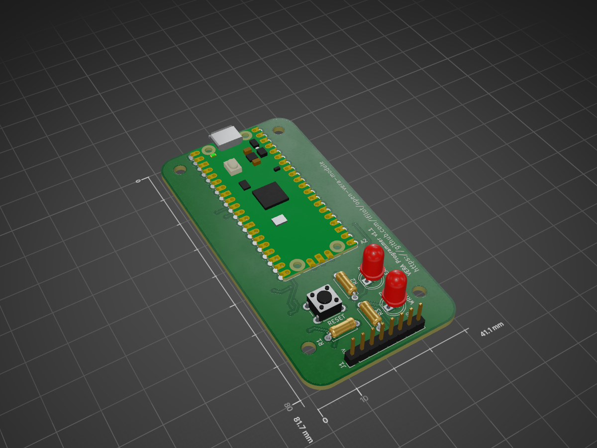
Vera programmer is an open-source printed circuit board by ifilot, from the ifilot/open-vera-module repository on GitHub, published under the MIT licence. It is a 2-layer board of 41.1 × 81.7 mm with 12 parts on 56 nets, routed with 138 tracks and 13 vias.
Its parts include 3 resistors, 2 diodes, 1 connector and 1 switch. It belongs with the interfaces and adapters boards and the RP2040 boards of this library.



VERA (Versatile Embedded Retro Adapter) is a self-contained FPGA video and audio module for retro-computing projects. It provides tile and bitmap graphics, sprites, programmable audio, PCM playback, and SPI/SD-card access through a straightforward host interface.
This repository contains the hardware, FPGA design, host bridge, programmer, desktop GUI, and documentation needed to build and use the module.
[!NOTE] Upstream attribution and independence: Open VERA Module is a community-maintained fork of the original VERA Module created by Frank van den Hoef. It preserves the original project’s history and VERA compatibility goals, but is an independent project and is not affiliated with, endorsed by, or an official release of Frank van den Hoef or the original VERA project. See NOTICE and LICENSING.md for attribution and licensing details.
| Path | Contents |
|---|---|
pcb/ | KiCad hardware designs for the VERA module and accessories. |
firmware/ | FPGA source and scripts for generating the flashable bitstream. |
driver/src/vera_driver/ | Arduino Mega 2560 serial-to-VERA bridge firmware. |
driver/gui/ | Qt desktop application for connecting to and testing a VERA module. |
toolchain/programmer/ | RP2040 programmer firmware and command-line tooling. |
docs/ | Sphinx documentation. |
The reproducible Docker build is the recommended way to generate a bitstream:
bash firmware/build-docker.shThe resulting flashable image is written to firmware/build/vera.bin. See the firmware README for local-toolchain builds and timing reports.
The bridge exposes VERA over USB serial using an Arduino Mega 2560. Compile and upload it with arduino-cli:
arduino-cli compile --fqbn arduino:avr:mega driver/src/vera_driver
arduino-cli upload --fqbn arduino:avr:mega --port <serial-port> driver/src/vera_driver
Consult the bridge documentation for the VERA bus pin mapping.
The GUI requires Qt 6 with the Widgets and SerialPort components. Configure and build it with CMake:
cmake -S driver/gui -B driver/gui/build
cmake --build driver/gui/build --parallel
On launch, the application attempts to connect to a detected bridge automatically; closing it resets the connected VERA module. The Windows installer is also available from the GUI installer workflow.
Project documentation lives in docs/. The published documentation is built by GitHub Actions; its current status is shown above. Start with docs/index.rst for the table of contents.
Contributions and issue reports are welcome. Please keep changes focused, include relevant build or test results, and follow the guidance in CONTRIBUTING.md.
The project is licensed by component: maintained hardware designs are released under CERN-OHL-S-2.0 and maintained software under GPL-3.0-or-later. Historic upstream material remains MIT-licensed where marked. See LICENSING.md for the complete licence map and NOTICE for attributions.
| Qty | Value | Footprint | References |
|---|---|---|---|
| 4 | MountingHole | MountingHole:MountingHole_3.2mm_M3 | H1, H2, H3, H4 |
| 2 | 560 | Resistor_THT:R_Axial_DIN0207_L6.3mm_D2.5mm_P7.62mm_Horizontal | R2, R3 |
| 1 | 10K | Resistor_THT:R_Axial_DIN0207_L6.3mm_D2.5mm_P7.62mm_Horizontal | R1 |
| 1 | Prog | Connector_PinHeader_2.54mm:PinHeader_1x08_P2.54mm_Vertical | J1 |
| 1 | READ | LED_THT:LED_D5.0mm | D2 |
| 1 | RESET | Button_Switch_THT:SW_PUSH_6mm | SW1 |
| 1 | RaspberryPi_Pico | Module:RaspberryPi_Pico_Common_Unspecified | A2 |
| 1 | WRITE | LED_THT:LED_D5.0mm | D3 |
It measures 41.1 × 81.7 mm and has 2 copper layers, 1.6 mm thick.
12 parts. The full list of its parts is on this page, with links to each part's symbol and footprint where PCBKit's library has them.
From the ifilot/open-vera-module repository on GitHub, at the commit this page was made from: the board is toolchain/programmer/pcb/vera-programmer.kicad_pcb and its schematic pcb/vera-full-audiojack/vera-full-audiojack.kicad_sch. PCBKit opens the board in the browser, with nothing to install.
Its repository publishes it under the MIT licence: you may reuse it on that licence's terms (keep the author's notice, and for a copyleft licence share your changes alike).
ifilot/open-vera-module
VERA (Versatile Embedded Retro Adapter) is a self-contained FPGA video and audio module for retro-computing projects.

ifilot/open-vera-module
VERA (Versatile Embedded Retro Adapter) is a self-contained FPGA video and audio module for retro-computing projects.

github-linguist/linguist
Language Savant. If your repository's language is being reported incorrectly, send us a pull request!


google/mozc-devices
Circuit diagrams and firmware source code for Gboard DIY keyboards


hackclub/OnBoard
💡 Join 1,000 teenagers and make your first PCB with a $100 grant!

VoronDesign/Voron-Tap
Tap is a nozzle-based z-probe for the V2 and Trident printer designs. The entire toolhead moves to trigger an optical switch. Tap offers many advantages:

stacksmashing/pico-tpmsniffer
A simple, very experimental TPM sniffer for LPC bus