
2 layers
Nrf bga
github-linguist/linguist
Language Savant. If your repository's language is being reported incorrectly, send us a pull request!
12 parts14kMIT
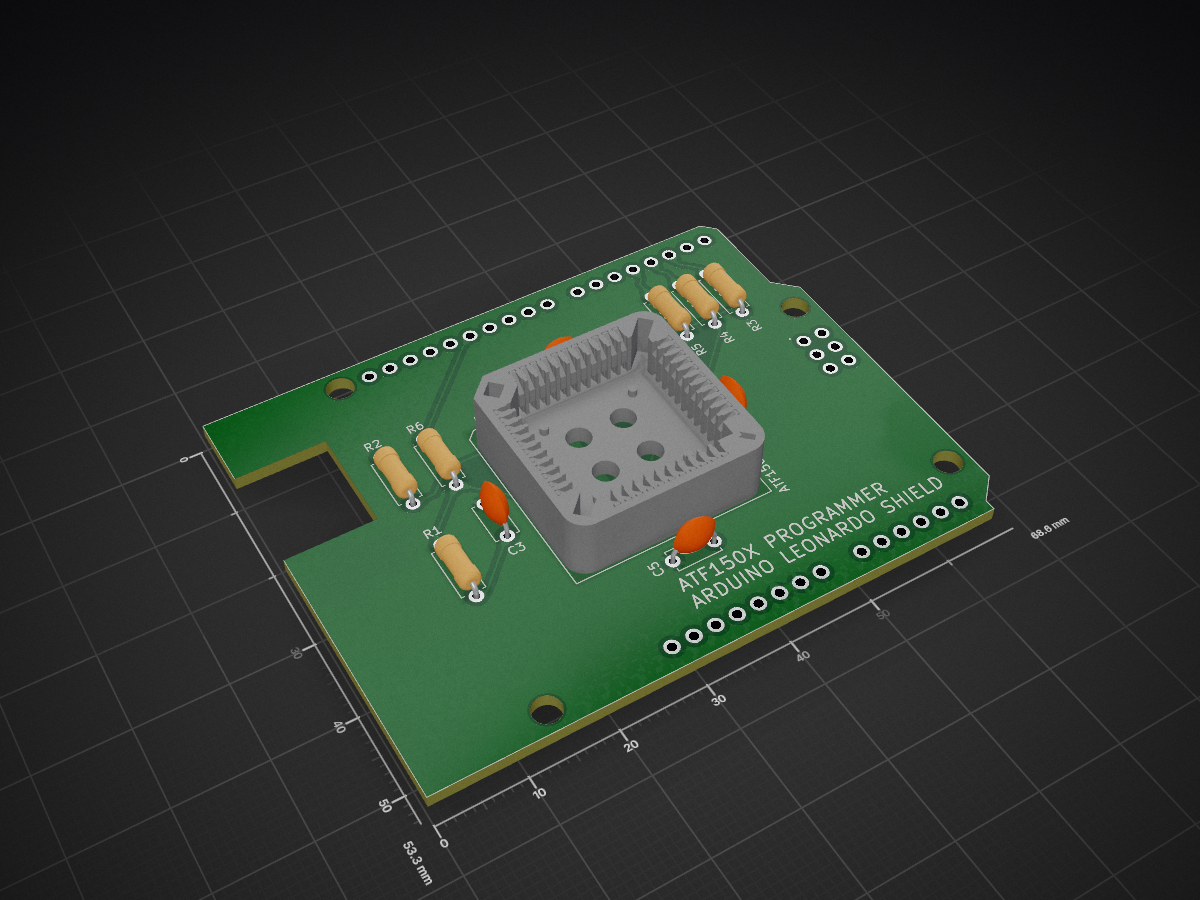
 ifilot/atf150x-programmer
Arduino Leonardo shield for programming ATF150X-type of CPLDs
Atf150x programmer is an open-source printed circuit board by ifilot, from the ifilot/atf150x-programmer repository on GitHub, published under the GPL-3.0 licence. It is a 2-layer board of 68.6 × 53.3 mm with 12 parts on 71 nets, routed with 97 tracks and 0 vias.
Its parts include 6 resistors, 4 capacitors and 1 IC. It belongs with the interfaces and adapters boards and the AVR (ATmega, ATtiny) and FPGA and CPLD boards of this library.


Program ATF1502AS and ATF1504AS chips with an Arduino Leonardo and a small open-source adapter board, instead of the expensive ATDH1150USB programmer and its vendor software.
These chips (CPLDs) hold a small digital-logic design that you create in a tool
such as WinCUPL. That tool produces a .jed file; this project writes that
file into the chip and checks that it arrived correctly.
pcb/atf150X-programmer,
fitted on an Arduino Leonardo..jed file for your design, for example made with WinCUPL.Not supported: ATF1502ASV/BE and other low-voltage variants, other chip sizes, several chips in one chain, and chips whose JTAG port has been switched off.
| What | Download (v0.3.0) |
|---|---|
| Desktop application for Windows (recommended) | Installer · Portable zip |
| Command-line tool | Windows · Linux |
| Arduino Leonardo firmware | Firmware (already included with the desktop application) |
Newer versions and checksums are on the latest release page.
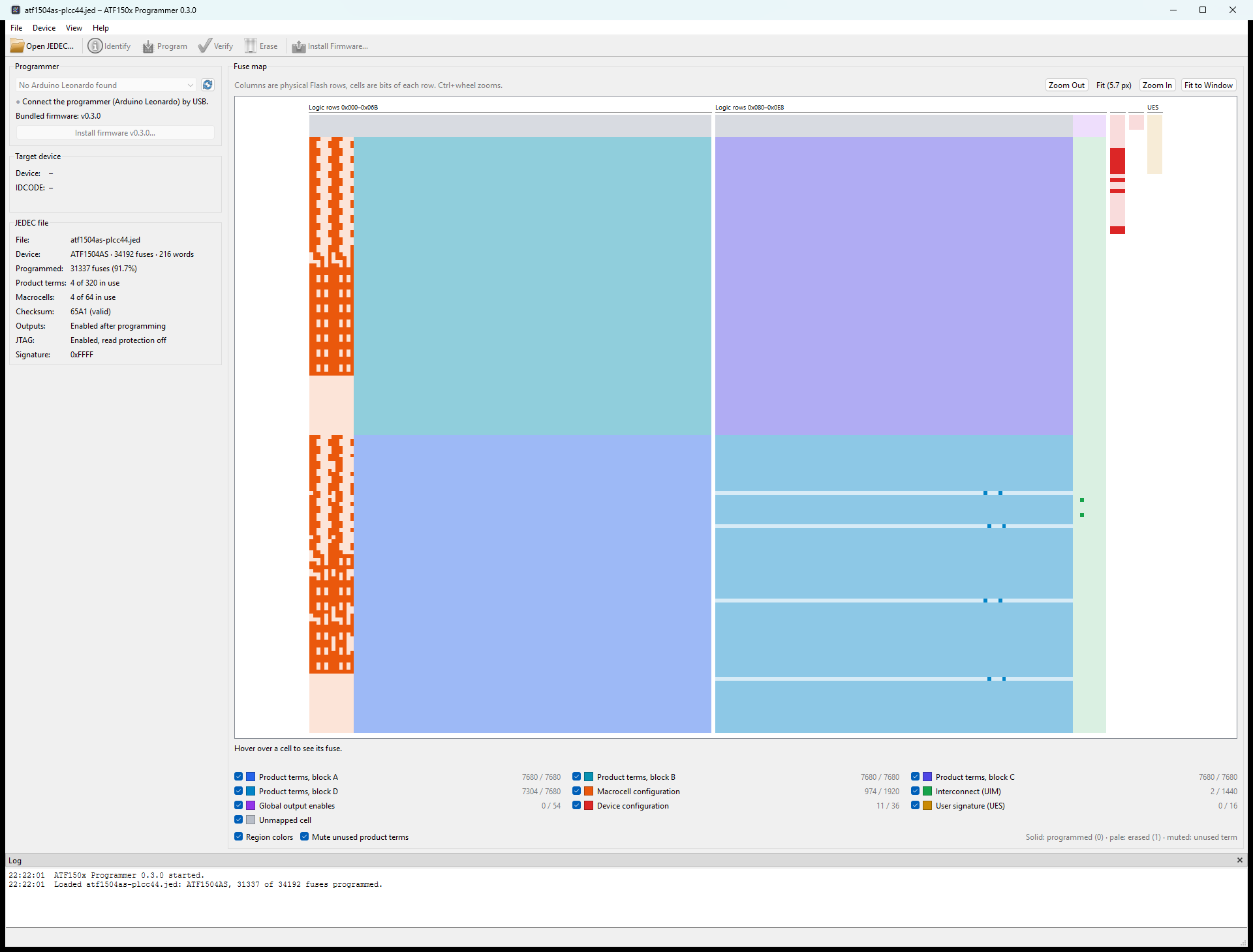
.jed file with Open JEDEC… or by dragging it onto the
window.The status bar and the log at the bottom tell you whether it succeeded.
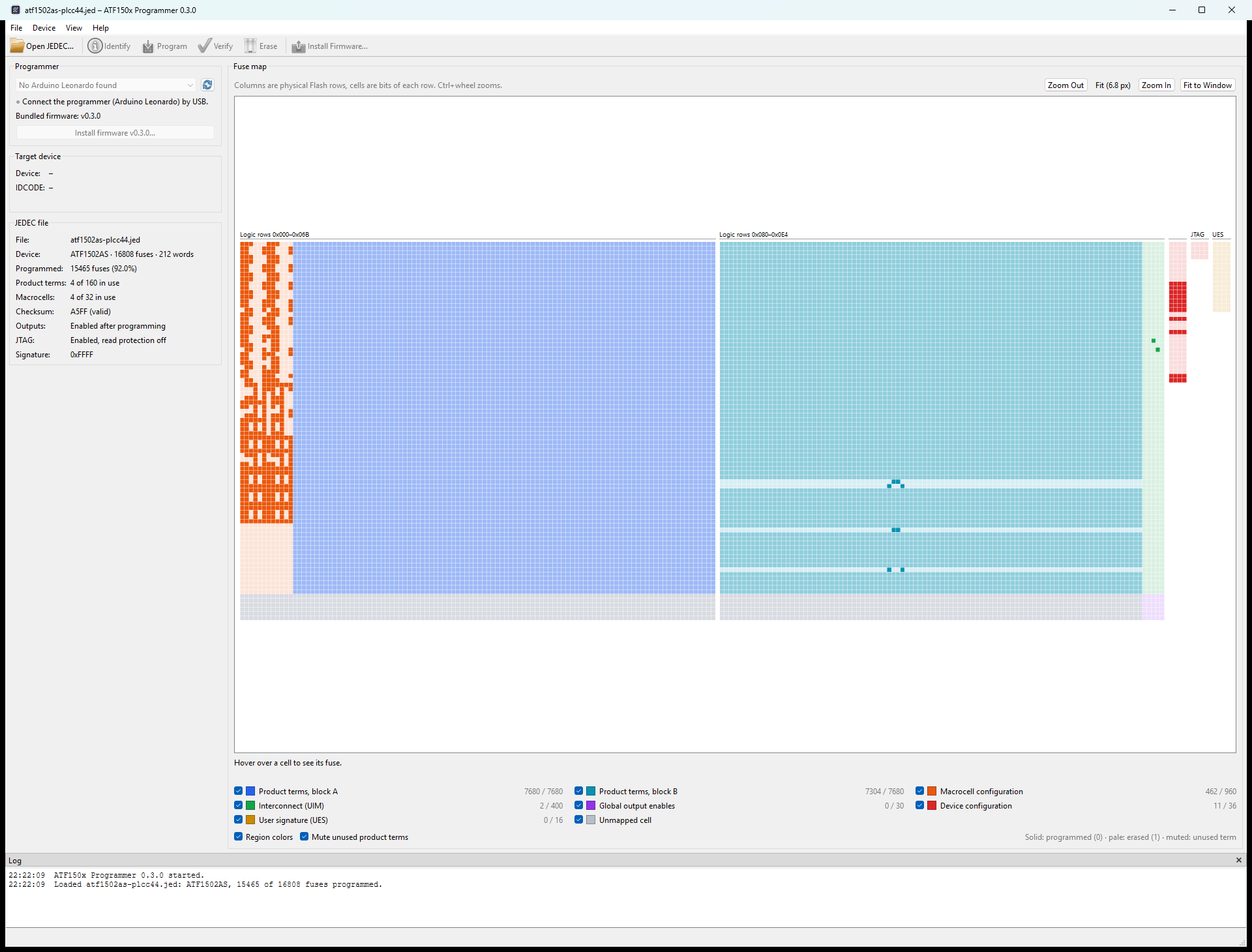 | 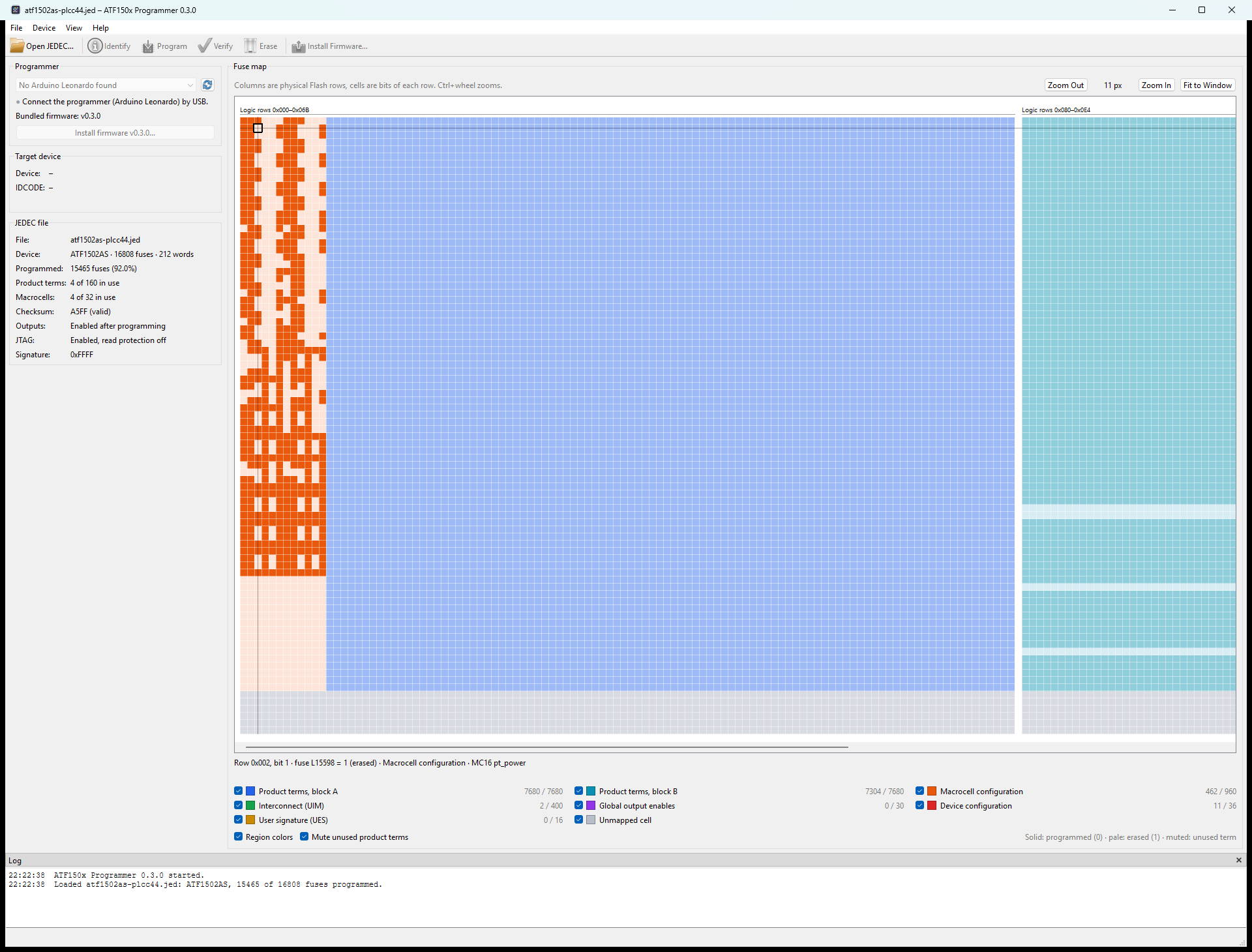 |
| An ATF1502AS design, fitted to the window. | Zoomed in; the cell under the mouse is described below the map. |
.jed file in WinCUPL, it is reloaded
automatically before programming.atfprog does the same as the desktop application from a terminal. Replace
COM3 with your Arduino's port (on Linux, for example /dev/ttyACM0). In
Windows PowerShell, type .\atfprog.exe instead of atfprog.
atfprog inspect design.jed            # check the file; does not touch the chip
atfprog scan --port COM3              # identify the chip
atfprog flash design.jed --port COM3  # erase, program and check
atfprog verify design.jed --port COM3 # compare chip and file
atfprog erase --port COM3             # erase the chip
atfprog --help
flash checks the .jed file before it touches the chip, and switches the new
design on only after every bit has been read back and compared. If programming
is interrupted, reconnect and run flash again. A nonzero exit status means
the operation failed.
/dev/ttyACM0. Add your user to the serial
group (usually dialout), then log out and in again.| JTAG | Leonardo pin | Series resistor |
|---|---|---|
| TDI | D2 | R3 |
| TCK | D3 | R4 |
| TDO | D4 | R5 |
| TMS | D12 | R6 |
The board uses ordinary GPIO pins, not the Leonardo's SPI header. Its 5V1 pin
supplies the +5V net. The firmware leaves the JTAG pins as inputs between
sessions and does not switch the chip's power. ATF1502AS reports IDCODE
0x0150203F; ATF1504AS reports 0x0150403F.
The software, firmware, tests, build configuration and documentation are
licensed under the GNU General Public License version 3 only
(GPL-3.0-only); see LICENSE. Copyright (c) 2026 ATF1502 programmer
contributors. Required upstream notices are kept in
third-party attribution. The PCB files keep their
CC BY-SA 4.0 license.
| Qty | Value | Footprint | References |
|---|---|---|---|
| 4 | 0.1uF | Capacitor_THT:C_Disc_D5.0mm_W2.5mm_P5.00mm | C2, C3, C4, C5 |
| 4 | 100 | Resistor_THT:R_Axial_DIN0207_L6.3mm_D2.5mm_P7.62mm_Horizontal | R3, R4, R5, R6 |
| 2 | 10k | Resistor_THT:R_Axial_DIN0207_L6.3mm_D2.5mm_P7.62mm_Horizontal | R1, R2 |
| 1 | ATF1502AS | Package_LCC:PLCC-44_THT-Socket | U4 |
| 1 | Arduino_Leonardo_Shield | Arduino:Arduino_Uno_Shield | XA1 |
It measures 68.6 × 53.3 mm and has 2 copper layers, 1.6 mm thick.
12 parts. The full list of its parts is on this page, with links to each part's symbol and footprint where PCBKit's library has them.
From the ifilot/atf150x-programmer repository on GitHub, at the commit this page was made from: the board is pcb/atf150X-programmer/atf150X-programmer.kicad_pcb and its schematic pcb/atf150X-programmer/atf150X-programmer.kicad_sch. PCBKit opens the board in the browser, with nothing to install.
Its repository publishes it under the GPL-3.0 licence: you may reuse it on that licence's terms (keep the author's notice, and for a copyleft licence share your changes alike).
github-linguist/linguist
Language Savant. If your repository's language is being reported incorrectly, send us a pull request!


google/mozc-devices
Circuit diagrams and firmware source code for Gboard DIY keyboards


hackclub/OnBoard
💡 Join 1,000 teenagers and make your first PCB with a $100 grant!

VoronDesign/Voron-Tap
Tap is a nozzle-based z-probe for the V2 and Trident printer designs. The entire toolhead moves to trigger an optical switch. Tap offers many advantages:

stacksmashing/pico-tpmsniffer
A simple, very experimental TPM sniffer for LPC bus