2 layers97.2 × 50.5 mm

 ieb/N2KEngine
N2K Single board engine monitor using a 328p
Attiny3226Board is an open-source printed circuit board by ieb, from the ieb/N2KEngine repository on GitHub. It is a 2-layer board of 97 × 54.3 mm with 73 parts on 52 nets, routed with 511 tracks and 13 vias.
It is built around the ATTINY3226-SU, AMS1117-5.0 and LM393, with the TJA1050 and S1J among its other parts. Its parts include 24 resistors, 17 capacitors, 13 diodes, 12 connectors and 5 ICs. It belongs with the AVR (ATmega, ATtiny) boards of this library.


This monitors an engine, mostly temperatures and fuel, emitting suitable N2K messages. Targeting a Volvo Penta D2-40. Code and pcb are based on the interface board in https://github.com/ieb/EngineManagement, however this time the pcb is from scratch using a Atmel 328p directly to make the unit more robust. The original has been in service for 3 years with no problems seen, outlasting the Volvo Penta MDI unit, which failed 2x in < 4 years. Ok, the replacement was based on relays following the Perkins schematic for the same engine, so not really hard to do.
Single board. If using a 328p chip you will need to flash the bootloader. See programBootLoader for details.
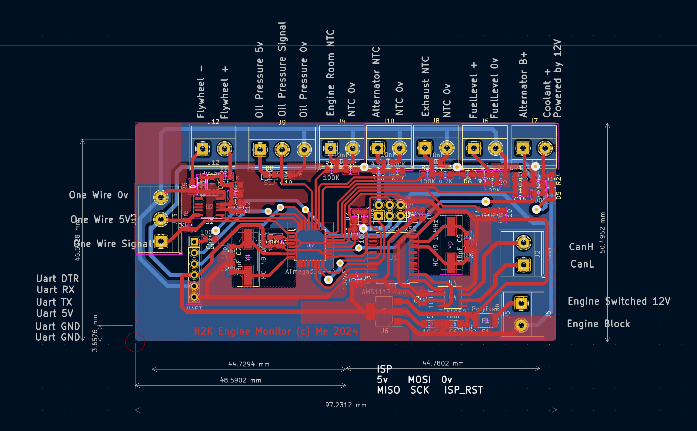
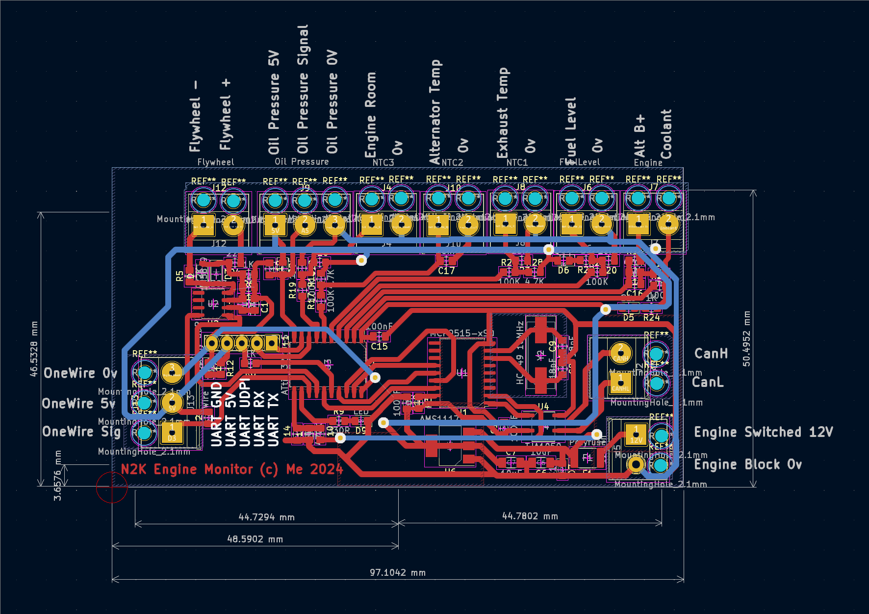
Setup starting with a new board, this is for 3226 which the preferred board.
The GND connection must be made to the engine block (star pattern) to avoid GND voltage differences when the anternator is charging. Do not GND on the battery as that will result in dips in the coolant temperature of 5C or more. The battery voltage will include the GND drop on the charging line.
The exhaust NCT should be connected to a part of the wet exhaust with good thermal connection to the inside of the exhaust. Do not connect to the elbow on the engine as this could result in false alarms when starting a warm engine. The trigger level is 45C or an 8C every 30s rise. Typically an exaust in UK waters on a D2-40 rests at 34-37C and rises rapidly should raw water fail.
after reducing memory requirements (580 used before), varies up an down a bit with debug.
attiny3226
RAM:   [==        ]  20.1% (used 619 bytes from 3072 bytes)
Flash: [========  ]  81.1% (used 26579 bytes from 32768 bytes)
NB, no malloc in use in code. Over 77% Flash usag pio inspect no longer works, however removing One wire code may give enough space for debug symbols to allow inspect to work
The status bits in PGN 127489 are set to indicate an alarm condition.
Alarm set levels and alarm clear levels are in enginesensors.h
WHen an alarm condition is set if the check engine, maintenance or emergency stop bits are set, they are not cleared when the alarm clears. Generally advisable to stop the engine and check.
Emergency stop will be set when temperatures are too high. Best to stop the engine before damage occurs.
Over Temperature status 1 bit 1 set when over temperature is suspected including coolant (> 97C), exhaust > 45C, alternator > 110C, engine room > 70C. Will also set check engine and engine emergency shutdown alarms.
Low oil pressure alarm is set when oil pressure is < 10psi.
If sensors fail then engine comms alarm is set.
Water flow alarm uses the wet exhaust silencer probe as a proxy for raw water flow. The probe is mounted on the silencer body, which is in direct contact with the wet exhaust but thermally isolated from the engine block and heat exchanger — so silencer temperature reflects exhaust gas vs raw water flow only, and is not biased by block temperature on a warm restart. Two independent triggers, both gated on engine running, past the start-up grace period, and not stopping:
A coolant-vs-exhaust convergence check was previously included but removed: on a warm restart the silencer takes several minutes to thermalize while coolant is already at operating temperature, producing a coolant–exhaust gap that approaches the trip margin under entirely healthy conditions.
The alarm clears only once exhaust drops below 38C (widened from 40C) to avoid chatter on a cooling elbow.
Charge indicator alarm is set when the alternator voltage is < 12.8V
Engine shutdown alarm will be set when the engine is shutting down.
Other alarms are not set at this time.
Use UDPI. I use the old, slow and slightly buggy jtag2udpi programmer loaded onto an Uno. I use https://github.com/ieb/jtag2updi forked just in case. After programming the Uno needs a 10uF cap between reset and ground to prevent a reset on the Uno when programming starts. The UDPI output is on Digital Pin 6 and connects via a 4K7 Resistor to the UDPI pin on the Attiny3226. The target board should be powered separately, and the serial monitor can remain attached while programming. Do not power the board using both a serial converter and the 12v power supply as this will cause the serial port to draw too much USB current and be shutdown. Programing setup is in platformio.ini. Before programming a fresh chip, set the fuses to set the CPU Frequency.
Fresh boards also need to go through a runing process , see tuning3226/
Obviously edit platform.ini with the correct serial ports for upload and monitoring.
pio run -e attiny3226 -t fusesThen upload code with an upload command. Fuses only need to be set once per chip.
pio run -e attiny3226 -t uploadTo monitor
pio device monitorThe 3226 board uses an internal oscilator due to lack of pins and so it needs tuning from a board with a quartz crystal as per https://github.com/SpenceKonde/megaTinyCore/blob/master/megaavr/extras/Ref_Tuning.md. The Tuning source needs to be https://github.com/SpenceKonde/megaTinyCore/tree/master/megaavr/libraries/megaTinyCore/examples/TuningSource uploaded onto a Uno or any 328p with pin 9 available. The UNO must have an real crystal not a resonator. The tuning code is https://github.com/SpenceKonde/megaTinyCore/tree/master/megaavr/libraries/megaTinyCore/examples/megaTinyTuner, but for these boards must be modified to use PB1 as the timing pin since this is exposed directly. (Oil pressure sense). Copies of both of these are in tuning as they needed minor modifications.
Can be built on any 328p suitably wired, however to build using the pcb design first flash a bootloader, see [programBootLoader/README.md] for details, then come back here.
Having flashed with the urbootloader connect a serial adapter configured for 5V to the serial header pins, adjust platform.ini to reflect the serial port and run
pio run -t uploadto monitor
pio device monitorDo not attempt to power the board both on the 12v line and through the serial port 5v at the same time. This will probably shutdown the USB port on your laptop (or worse produce some smoke) Monitoring over serial can be done provided only GND, TX and RX are attached. Ie no power from the serial adapter.
Critical that this chip as a 100nF decoupling capacitor. Without it it will generate pulses from power supply noise with the inputs shorted together. See schematic. LTSpice models don't predict this behavior.
Stores upto 29 events in EEPROM, with a 15s resolution and one of upto 255 types. All the following PGNS have standard priorietary PGN format + a Function code byte. The Manufactore code is 2046 and the Industry is Marine, ie 4.
Since Raymarine instuments display only a asubset of PGNs, some are beeing abused to get critical temperatures avialable on the insturments.
Standard Packet proprietary, 8 bytes
| Field | Length | Value | Description | |-----------------------------------------------------| | 1 | 11 bits| 2046 | Manufacturer code | | 2 | 2 bits | | Rserved | | 3 | 3 bits | 4 (0b100) | Industry Code | | 4 | 8 bits | | Requst Function Number | | 5 | 5 bytes| | reserved/payload |
| Function | Description | Valid PGN | Response |
|---|---|---|---|
| 11 | Get events | 65305L | Events PGN 130817L Functon 12 |
| 12 | Get events response | 130817L | List of events |
| 13 | Clear events | 65305L | ACK PGN 65305L Functon 14, no payload |
| 14 | Clear events ACK | 65305L | Ack clear events, no payload |
| Field | Length | Value | Description |
|---|---|---|---|
| 1 | 11 bits | 2046 | Manufacturer code |
| 2 | 2 bits | Rserved | |
| 3 | 3 bits | 4 (0b100) | Industry Code |
| 4 | 8 bits | Requst Function Number |
| Field | Length | Value | Description |
|---|---|---|---|
| 4 | 1 byte | uint8_t | Number of events |
| 5+(n*4) | 1 byte | uint8_t | Event ID |
| 6+(n*4) | 3 bytes | 3Byte UDouble 0.001 | Engine Hours of event (15s resolution) |
| Event ID | Meaning |
|---|---|
| 0 | Current engine hours, no event |
| 1 | Engine Stop |
| 2 | Low Oil Pressure |
| 3 | High Coolant Temperature |
| 4 | High Exhaust Temperature |
| 5 | High Alternator Temperature |
| 6 | High Engine Room Temperature |
The board currently runs of switched engine power, so to read fuel tank and batteries the engine has to be turned on. This is good, since power consumption becomes irrelevant although its typically < 80mA. I could optimize so that the board could be powered from the Can bus, but probably wont. Better to have it off when not relevant.. eg when sailing.
Had been motoring for about 45m, 2.2K rpm all stable.
Exhaust elbow temperature rises rapidly 22C over 1m vs 8C over the same period for the engine coolant temperature, although at the time no raw water alarm sounded as the limit was set at 80C and there was no display showing exhaust temperature.
Exhaust elbow temperature seems to be a strong indicator of water flow once the engine is running at temperature.
| Qty | Value | Footprint | References |
|---|---|---|---|
| 9 | 10K | Resistor_SMD:R_0805_2012Metric_Pad1.20x1.40mm_HandSolder | R3, R7, R9, R12, R17, R19, R23, R25, R27 |
| 9 | S1J | Diode_SMD:D_0805_2012Metric_Pad1.15x1.40mm_HandSolder | D5, D6, D7, D8, D11, D12, D13, D14, D15 |
| 5 | 10nF | Capacitor_SMD:C_0805_2012Metric_Pad1.18x1.45mm_HandSolder | C17, C18, C19, C20, C23 |
| 4 | 100nF | Capacitor_SMD:C_0805_2012Metric_Pad1.18x1.45mm_HandSolder | C1, C10, C15, C24 |
| 3 | 4.7K | Resistor_SMD:R_0805_2012Metric_Pad1.20x1.40mm_HandSolder | R16, R18, R28 |
| 3 | 470nF | Capacitor_SMD:C_0805_2012Metric_Pad1.18x1.45mm_HandSolder | C11, C14, C16 |
| 3 | 4K7 | Resistor_SMD:R_0805_2012Metric_Pad1.20x1.40mm_HandSolder | R1, R2, R26 |
| 2 | 100K | Resistor_SMD:R_0805_2012Metric_Pad1.20x1.40mm_HandSolder | R10, R14 |
| 2 | 10uF | Capacitor_SMD:C_1206_3216Metric_Pad1.33x1.80mm_HandSolder | C6, C7 |
| 2 | 18pF | Capacitor_SMD:C_0805_2012Metric_Pad1.18x1.45mm_HandSolder | C8, C9 |
| 2 | 22K | Resistor_SMD:R_0805_2012Metric_Pad1.20x1.40mm_HandSolder | R4, R5 |
| 2 | 47K | Resistor_SMD:R_0805_2012Metric_Pad1.20x1.40mm_HandSolder | R11, R15 |
| 2 | LED | LED_SMD:LED_0805_2012Metric_Pad1.15x1.40mm_HandSolder | D1, D2 |
| 2 | SJ1 | Diode_SMD:D_SOD-123 | D3, D4 |
| 1 | HC-49 16MHz | Crystal:Crystal_SMD_HC49-SD | Y2 |
| 1 | 10uF | Capacitor_SMD:C_0805_2012Metric_Pad1.18x1.45mm_HandSolder | C21 |
| 1 | 12V In | TerminalBlock_Phoenix:TerminalBlock_Phoenix_MKDS-1,5-2-5.08_1x02_P5.08mm_Horizontal | J5 |
| 1 | 1K | Resistor_SMD:R_0805_2012Metric_Pad1.20x1.40mm_HandSolder | R22 |
| 1 | 1Wire | TerminalBlock_Phoenix:TerminalBlock_Phoenix_MKDS-1,5-3-5.08_1x03_P5.08mm_Horizontal | J13 |
| 1 | 220K | Resistor_SMD:R_0805_2012Metric_Pad1.20x1.40mm_HandSolder | R8 |
| 1 | 470R | Resistor_SMD:R_0805_2012Metric_Pad1.20x1.40mm_HandSolder | R6 |
| 1 | AMS1117-5.0 | Package_TO_SOT_SMD:SOT-223-3_TabPin2 | U6 |
| 1 | ATtiny3226-S | Package_SO:SOIC-20W_7.5x12.8mm_P1.27mm | U3 |
| 1 | Attiny UDPI | Connector_PinHeader_2.54mm:PinHeader_1x05_P2.54mm_Vertical | J3 |
| 1 | CAN | TerminalBlock_Phoenix:TerminalBlock_Phoenix_MKDS-1,5-2-5.08_1x02_P5.08mm_Horizontal | J2 |
| 1 | Engine | TerminalBlock_Phoenix:TerminalBlock_Phoenix_MKDS-1,5-2-5.08_1x02_P5.08mm_Horizontal | J7 |
| 1 | Flywheel | TerminalBlock_Phoenix:TerminalBlock_Phoenix_MKDS-1,5-2-5.08_1x02_P5.08mm_Horizontal | J12 |
| 1 | FuelLevel | TerminalBlock_Phoenix:TerminalBlock_Phoenix_MKDS-1,5-2-5.08_1x02_P5.08mm_Horizontal | J6 |
| 1 | LM393 | Package_SO:SOIC-8_3.9x4.9mm_P1.27mm | U2 |
| 1 | MCP2515-xSO | Package_SO:SOIC-18W_7.5x11.6mm_P1.27mm | U1 |
| 1 | NTC1 | TerminalBlock_Phoenix:TerminalBlock_Phoenix_MKDS-1,5-2-5.08_1x02_P5.08mm_Horizontal | J8 |
| 1 | NTC2 | TerminalBlock_Phoenix:TerminalBlock_Phoenix_MKDS-1,5-2-5.08_1x02_P5.08mm_Horizontal | J10 |
| 1 | NTC3 | TerminalBlock_Phoenix:TerminalBlock_Phoenix_MKDS-1,5-2-5.08_1x02_P5.08mm_Horizontal | J4 |
| 1 | Oil Pressure | TerminalBlock_Phoenix:TerminalBlock_Phoenix_MKDS-1,5-3-5.08_1x03_P5.08mm_Horizontal | J9 |
| 1 | Polyfuse | Fuse:Fuse_1812_4532Metric_Pad1.30x3.40mm_HandSolder | F1 |
| 1 | StopSolenoid | Connector_PinSocket_2.54mm:PinSocket_1x01_P2.54mm_Vertical | J1 |
| 1 | TJA1050 | Package_SO:SOIC-8_3.9x4.9mm_P1.27mm | U4 |

ieb/N2KEngineEsp32
N2K Engine Interface with BLE built around an ESP32 and ADS1115 ADCs


ieb/N2KNMEA0183Wifi
Exposes NMEA2000 and BMS data over BLE for Apps to use. Also supports Wifi/http/tcp/udp services.


hb020/batterymeter
Handheld Battery AC and Time Domain characterization tool on Attiny series 2

mayermakes/MyGenWashy
Generic washing Machine Controller - Result of the TuttleButtle Hackathon 2025
It measures 97 × 54.3 mm and has 2 copper layers, 1.6 mm thick.
73 parts, built around the ATTINY3226-SU, AMS1117-5.0, LM393 and TJA1050. The full list of its parts is on this page, with links to each part's symbol and footprint where PCBKit's library has them.
From the ieb/N2KEngine repository on GitHub, at the commit this page was made from: the board is pcb/caninterfaceboard/attiny3226Board.kicad_pcb and its schematic pcb/caninterfaceboard/atmel328pBoard.kicad_sch. PCBKit opens the board in the browser, with nothing to install.
Its repository states no licence, so its author keeps all rights: ask ieb before reusing the design.