2 layers121 × 156.5 mm
UGV
ugv-dtu/electronics_2026
This repository contains 2 firmware projects, each for a different operational mode of the Rover. Only one folder is flashed to Teensy at a time — either autonomous or manual.
99 parts

 ideocentric/four-tone
Arduino fan organ: four 12 V blowers voicing 3D printed recorder-style pipes
Four tone driver is an open-source printed circuit board by ideocentric, from the ideocentric/four-tone repository on GitHub. It is a 2-layer board of 130 × 70 mm with 54 parts on 48 nets, routed with 178 tracks and 61 vias.
It is built around the AO3400A, B2B-XH-A and SS14. Its parts include 18 resistors, 12 diodes, 9 connectors, 6 transistors and 5 capacitors.


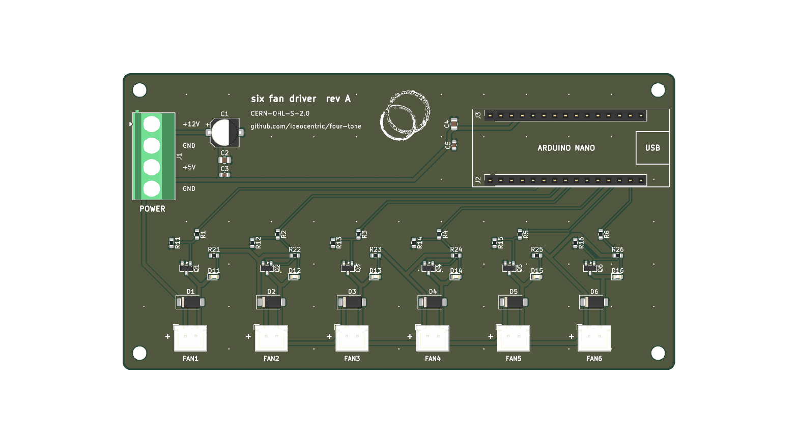
An Arduino Nano carrier board with six low-side MOSFET fan channels. four-tone uses four of them; the other two are spare for other projects. It is designed for JLCPCB fabrication and assembly, and rev A was ordered on 2026-09-15.
| File | What it is |
|---|---|
four-tone-driver.kicad_sch | Schematic (KiCad 9). PDF |
four-tone-driver.kicad_pcb | Board layout (KiCad 9) |
four-tone-driver.kicad_pro | Project settings, including the Power net class |
fabrication/rev-a/ | Gerbers, drill files, BOM and CPL as ordered, with the export settings |
The KiCad files keep the project's original four-tone-driver name; the board
itself is titled "six fan driver". Every symbol carries its JLCPCB/LCSC part
number in an LCSC field.
| Designators | Qty | Part | Package | LCSC | JLC type |
|---|---|---|---|---|---|
| Q1-Q6 | 6 | AO3400A N-MOSFET, 30 V 5.7 A | SOT-23 | C20917 | Basic |
| D1-D6 | 6 | SS14 Schottky flyback diode, 1 A 40 V | SMA | C2480 | Basic |
| D11-D16 | 6 | Red LED, channel indicator | 0603 | C2286 | Basic |
| R1-R6 | 6 | 1 k gate resistor | 0603 | C21190 | Basic |
| R11-R16 | 6 | 100 k gate pull-down | 0603 | C25803 | Basic |
| R21-R26 | 6 | 4.7 k LED resistor | 0603 | C23162 | Basic |
| C1 | 1 | 100 uF 25 V electrolytic, 12 V bulk | SMD 6.3 x 7.7 mm | C72477 | Extended |
| C2, C4 | 2 | 10 uF 25 V X5R, 12 V and 5 V bulk | 0805 | C15850 | Basic |
| C3, C5 | 2 | 100 nF 50 V X7R, 12 V and 5 V decoupling | 0603 | C14663 | Basic |
| J1 | 1 | 4-pin screw terminal, 5.08 mm | THT | C2915641 | Extended |
| J2, J3 | 2 | 1x15 female header, 2.54 mm (Nano socket) | THT | C7499333 | Extended |
| J11-J16 | 6 | JST B2B-XH-A, 2-pin vertical (genuine JST) | THT | C158012 | Extended |
Availability was checked on 2026-09-15 through tscircuit's jlcsearch mirror of the JLCPCB catalogue, and every line was in stock. Stock changes, so re-check in JLCPCB's BOM tool when ordering.
+5V pin directly through the socket,
bypassing its regulator. VIN is not connected. The Nano reference design has
a Schottky diode on USB VBUS, so the supply cannot back-feed a computer while
USB is plugged in for programming. Clones vary; check the ones you use.| Channel | Connector | Nano pin | PWM timer (Nano) | four-tone firmware |
|---|---|---|---|---|
| 1 | J11, FAN1 | D3 | Timer2, ~490 Hz | pipe 1 |
| 2 | J12, FAN2 | D5 | Timer0, ~980 Hz | pipe 2 |
| 3 | J13, FAN3 | D6 | Timer0, ~980 Hz | pipe 3 |
| 4 | J14, FAN4 | D9 | Timer1, ~490 Hz | pipe 4 |
| 5 | J15, FAN5 | D10 | Timer1, ~490 Hz | spare |
| 6 | J16, FAN6 | D11 | Timer2, ~490 Hz | spare |
Channels follow the order of the pins along the Nano's header, so the six gate traces fan out without crossing. D13 is avoided: it has no PWM, and the bootloader flashes its LED at every reset, which would blip a fan.
Module:Arduino_Nano
footprint.Power net class
(+12 V, +5 V, GND, FANn_DRV) uses 0.8 mm tracks with 0.25 mm clearance;
everything else is 0.3 mm with 0.2 mm clearance.github.com/ideocentric/four-tone, which CERN-OHL-S asks
products to carry. The ensō house mark sits beside that block
(source: ../art/enso-oro.svg). FAN1-FAN6 labels are on
the board-edge side of the connectors with + beside pin 1, and an outline of
the Nano's USB connector shows which way round the Nano goes.| Qty | Value | Footprint | References |
|---|---|---|---|
| 6 | 100k | Resistor_SMD:R_0603_1608Metric | R11, R12, R13, R14, R15, R16 |
| 6 | 1k | Resistor_SMD:R_0603_1608Metric | R1, R2, R3, R4, R5, R6 |
| 6 | 4.7k | Resistor_SMD:R_0603_1608Metric | R21, R22, R23, R24, R25, R26 |
| 6 | AO3400A | Package_TO_SOT_SMD:SOT-23 | Q1, Q2, Q3, Q4, Q5, Q6 |
| 6 | B2B-XH-A | Connector_JST:JST_XH_B2B-XH-A_1x02_P2.50mm_Vertical | J11, J12, J13, J14, J15, J16 |
| 6 | Red | LED_SMD:LED_0603_1608Metric | D11, D12, D13, D14, D15, D16 |
| 6 | SS14 | Diode_SMD:D_SMA | D1, D2, D3, D4, D5, D6 |
| 4 | M3 | MountingHole:MountingHole_3.2mm_M3 | H1, H2, H3, H4 |
| 2 | 100nF | Capacitor_SMD:C_0603_1608Metric | C3, C5 |
| 2 | 10uF 25V | Capacitor_SMD:C_0805_2012Metric | C2, C4 |
| 2 | Socket 1x15 | Connector_PinSocket_2.54mm:PinSocket_1x15_P2.54mm_Vertical | J2, J3 |
| 1 | 100uF 25V | Capacitor_SMD:CP_Elec_6.3x7.7 | C1 |
| 1 | PWR 12V/5V | TerminalBlock_Phoenix:TerminalBlock_Phoenix_MKDS-1,5-4-5.08_1x04_P5.08mm_Horizontal | J1 |
It measures 130 × 70 mm and has 2 copper layers, 1.6 mm thick.
54 parts, built around the AO3400A, B2B-XH-A and SS14. The full list of its parts is on this page, with links to each part's symbol and footprint where PCBKit's library has them.
From the ideocentric/four-tone repository on GitHub, at the commit this page was made from: the board is hardware/pcb/four-tone-driver.kicad_pcb and its schematic hardware/pcb/four-tone-driver.kicad_sch. PCBKit opens the board in the browser, with nothing to install.
Its repository states no licence, so its author keeps all rights: ask ideocentric before reusing the design.
ugv-dtu/electronics_2026
This repository contains 2 firmware projects, each for a different operational mode of the Rover. Only one folder is flashed to Teensy at a time — either autonomous or manual.


gustebeast/public-steel-guitar
A pedal steel guitar you can build yourself, from parts anyone can buy.


BoltzRnD/SmartPrintCoreH7x
STM32H7 based Robust and Open Source 3D Printer Mainboard

xtech/hw-openmower-universal
This hardware version is in beta state. Expect for things to not work at the current state!
