2 layers20.5 × 24.8 mm

 ide/tusb320-breakout-board2
breakout board for the Texas Instruments TUSB320 chip and a USB-C connector (16+8 dummy pins)
Tusb320-breakout board is an open-source printed circuit board by ide, from the ide/tusb320-breakout-board repository on GitHub, published under the MIT licence. It is a 2-layer board of 11.4 × 32.5 mm with 8 parts on 19 nets, routed with 96 tracks and 11 vias.
Its parts include 3 connectors, 2 capacitors, 2 resistors and 1 IC. It belongs with the interfaces and adapters and microcontroller boards boards of this library.
This PCB is a breakout board for the Texas Instruments TUSB320 chip and a USB-C connector (16+8 dummy pins).
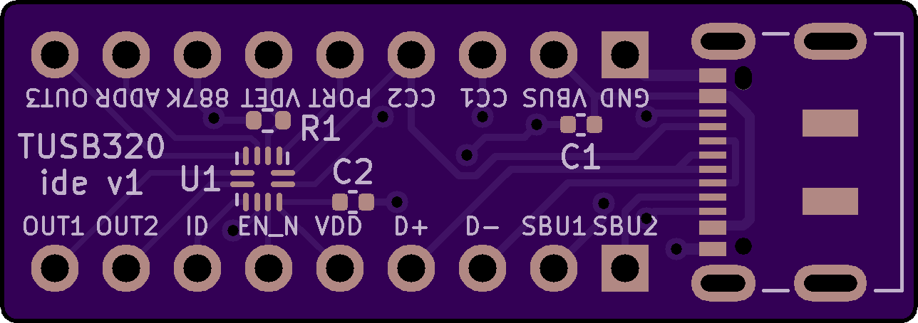
TBA
| Reference | Part description | Size | Example part # |
|---|---|---|---|
| R1 | 887K ohm resistor | 0402 | ERJ-2RKF8873X |
| R2 | 0 ohm resistor (optional) | 0402 | ERJ-2GE0R00X |
| C1 | 1μF 35V capacitor | 0402 | GRM155R6YA105KE11D |
| C2 | 0.1μF 5V capacitor | 0402 | 04025C104KAT2A |
| J1 | USB-C connector (16+8 dummy pins) | Surface mount, right angle, through hole | DX07S016JA1R1500 |
| J2, J3 | 1x9 male through hole headers | PRPC009SAAN-RC | |
| U1 | TUSB320, TUSB320LI, TUSB320LAI | 12-X2QFN | TUSB320LAIRWBR |
| Qty | Value | Footprint | References |
|---|---|---|---|
| 1 | 0.1μF | Capacitor_SMD:C_0402_1005Metric | C2 |
| 1 | 0K | Resistor_SMD:R_0402_1005Metric | R2 |
| 1 | 1μF | Capacitor_SMD:C_0402_1005Metric | C1 |
| 1 | 887K | Resistor_SMD:R_0402_1005Metric | R1 |
| 1 | Left Header Pins | Connector_PinHeader_2.54mm:PinHeader_1x09_P2.54mm_Vertical | J2 |
| 1 | Right Header Pins | Connector_PinHeader_2.54mm:PinHeader_1x09_P2.54mm_Vertical | J3 |
| 1 | TUSB320 | Package_DFN_QFN:Texas_X2QFN-12_1.6x1.6mm_P0.4mm | U1 |
| 1 | USB-C Receptacle (USB 2.0) | Connector_USB:USB_C_Receptacle_JAE_DX07S016JA1R1500 | J1 |

joeycastillo/Sensor-Watch
A board replacement for the classic Casio F-91W wristwatch

rusefi/rusefi
rusefi - GPL internal combustion engine control unit

hoglet67/RGBtoHDMI
Bare-metal Raspberry Pi project that provides pixel-perfect sampling of Retro Computer RGB/YUV video and conversion to HDMI

shanteacontrols/OpenDeck
A platform for building interactive control and sensing devices using MIDI and OSC built with Zephyr RTOS.

hackclub/OnBoard
💡 Join 1,000 teenagers and make your first PCB with a $100 grant!

dangiu/PicoMemcard
Emulating PSX Memory Card (or controller) using a Raspberry Pi Pico

OLIMEX/DIY-LAPTOP
Do It Yourself Open Source Hardware and Software Modular Hacker's Friendly Laptop
It measures 11.4 × 32.5 mm and has 2 copper layers, 1.6 mm thick.
8 parts. The full list of its parts is on this page, with links to each part's symbol and footprint where PCBKit's library has them.
From the ide/tusb320-breakout-board repository on GitHub, at the commit this page was made from: the board is tusb320-breakout-board.kicad_pcb and its schematic tusb320-breakout-board.kicad_sch. PCBKit opens the board in the browser, with nothing to install.
Its repository publishes it under the MIT licence: you may reuse it on that licence's terms (keep the author's notice, and for a copyleft licence share your changes alike).