2 layers103 × 30.5 mm
 ID6763Fall2016/Transitnotifier_RedGuppy
This is the transit notifier project called Buzz Clock. You will need the following hardware and software to build the Buzz Clock:
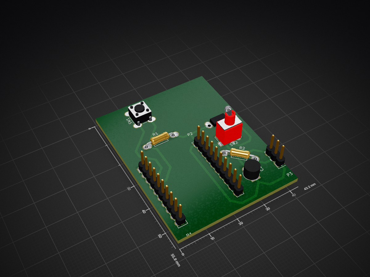
WiFiNeoClockHeader is an open-source printed circuit board by ID6763Fall2016, from the ID6763Fall2016/Transitnotifier_RedGuppy repository on GitHub. It is a 2-layer board of 43.2 × 55.9 mm with 9 parts on 22 nets, routed with 50 tracks and 0 vias.
Its parts include 3 connectors, 2 resistors, 2 switches and 1 capacitor.

This is the transit notifier project called Buzz Clock. You will need the following hardware and software to build the Buzz Clock:
Hardware:
Software:
The working code resides in the NextBusGT folder. After connecting the hardwares together and connecting ESP8266 to your laptop, you need to modify the code with your wifi SSID and Password then upload the code to the ESP8266 and it will start retrieve the data from the xml provided by http://gtbuses.herokuapp.com.

If you wish to make your own PCB instead of using a breadboard for the setup you can start with our CAD files in the WiFiNeoClock director. We used KiCad to create the board. Additional information on working with kiCad can be found at.. http://kicad-pcb.org/
| Qty | Value | Footprint | References |
|---|---|---|---|
| 2 | CONN_01X10 | Pin_Headers:Pin_Header_Straight_1x10 | P1, P2 |
| 2 | R | Resistors_ThroughHole:Resistor_Horizontal_RM10mm | R1, R2 |
| 1 | Battery | Pin_Headers:Pin_Header_Straight_1x02 | BT1 |
| 1 | CONN_01X03 | Pin_Headers:Pin_Header_Straight_1x03 | P3 |
| 1 | CP1 | Capacitors_ThroughHole:C_Radial_D5_L11_P2.5 | C1 |
| 1 | SW_PUSH | Buttons_Switches_ThroughHole:SW_PUSH_6mm | SW1 |
| 1 | Switch_SPDT_x2 | Buttons_Switches_ThroughHole:SW_NKK_G1xJP | SW2 |


FrameworkComputer/ExpansionCards
Reference designs and documentation to create Expansion Cards for the Framework Laptop

VoronDesign/Voron-Hardware
Cool Hardware designed by the Voron Design group

hackclub/OnBoard
💡 Join 1,000 teenagers and make your first PCB with a $100 grant!


adamws/kicad-kbplacer
KiCad plugin for automatic keyboard's key placement and routing
It measures 43.2 × 55.9 mm and has 2 copper layers, 1.6 mm thick.
9 parts. The full list of its parts is on this page, with links to each part's symbol and footprint where PCBKit's library has them.
From the ID6763Fall2016/Transitnotifier_RedGuppy repository on GitHub, at the commit this page was made from: the board is WiFiNeoClock/WiFiNeoClockHeader.kicad_pcb. PCBKit opens the board in the browser, with nothing to install.
Its repository states no licence, so its author keeps all rights: ask ID6763Fall2016 before reusing the design.