Skip to the content
2 layers209 × 209 mmPowerDistributionBoards, the printed circuit board in 3D

PowerDistributionBoards

icchalmers/WordClock_v2.02

This is a work-in-progress build of a word clock. It was originally my final project as part Fab Academy 2015 at Fab Lab Strathclyde. You can follow the inital evolution of the clock on my class website.

Size
209 × 209 mm
Copper layers
2
Thickness
1.6 mm
Parts
35
Nets
36
Pads
80
Tracks, vias
145, 0
Routed
Yes
KiCad
KiCad 4
Created
10 Feb 2015
Updated
3 Jul 2017

Overview

PowerDistributionBoards is an open-source printed circuit board by icchalmers, from the icchalmers/WordClock_v2.0 repository on GitHub. It is a 2-layer board of 209 × 209 mm with 35 parts on 36 nets, routed with 145 tracks and 0 vias.

Its parts include 22 ICs, 8 connectors and 1 capacitor.

README

README.md

WordClock_v2.0

This is a work-in-progress build of a word clock. It was originally my final project as part Fab Academy 2015 at Fab Lab Strathclyde. You can follow the inital evolution of the clock on my class website. The content is also mirrored to my GitHub Pages site.

This clock is an evolution of WordClock_v1.0.
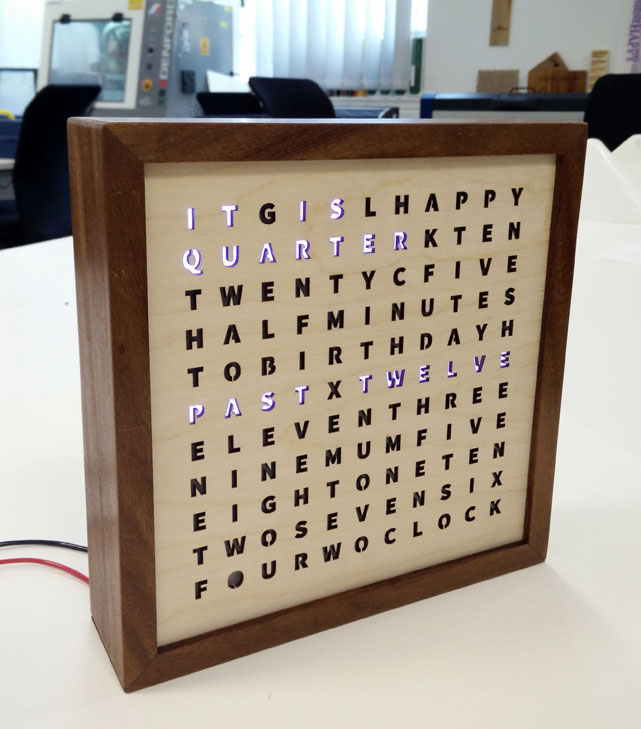
WordClock

Project Parts

Model

The 'Model' folder contains all the Autodesk Inventor 2015 CAD files for the clock.

The file Model/wordClock.ipt is VERY customisable, but has no mounting holes for electronics or any mechanism to support the LED strips.

The 'Model/SolidifiedClockToMake' folder contains a locked down version of the clock i.e. it uses a grid of 11x11. Some parameters may or may not still be adjustable. It has additional holes added to the middle plate for mounting control electronics and holding the LED strips in place.

The main file for the clock is wordClock_NonParametric.ipt. The other .ipt files are the individual pieces and are derived from wordClock_NonParametric.ipt. They have been compensated for laser kerf using the "kerf" parameter in the master model.

The file PartsForExport.dwg has a layout of each of the individual parts. If you change a parameter in the master model, update the individual parts and then update the .dwg.

The lettering is added in CorelDraw - Inventor is a bit rubbish at handling text. I used a modified version of Source Sans Pro i.e. I added little structures to support the internal parts of letters.

hw

The 'hw' folder has the KiCAD files for the two PCB designs: the main control board and the power distribution boards. The power distribution boards also help hold the LED strips in place.

Parts

35
QtyValueFootprintReferences
11WS2812b_Strip_InFabLibrary:WS2812b_strip_connU1, U4, U5, U8, U9, U12, U13, U16, U17, U20, U21
11WS2812b_Strip_OutFabLibrary:WS2812b_strip_connU2, U3, U6, U7, U10, U11, U14, U15, U18, U19, U22
25V+_OutSocket_Strips:Socket_Strip_Straight_1x01P6, P8
2GND_OutSocket_Strips:Socket_Strip_Straight_1x01P5, P7
15V+_InSocket_Strips:Socket_Strip_Straight_1x01P2
1CPCapacitors_Elko_ThroughHole:Elko_vert_11.5x8mm_RM3.5C1
1GND_InSocket_Strips:Socket_Strip_Straight_1x01P3
1WS2812b_inSocket_Strips:Socket_Strip_Straight_1x01P1
1WS2812b_outSocket_Strips:Socket_Strip_Straight_1x01P4

The 31 most common of 35 parts.

More from icchalmers/WordClock_v2.0

1
  • 2 layers209 × 16.5 mmPowerDistributionBoards SingleSide, the printed circuit board in 3D

    PowerDistributionBoards SingleSide

    icchalmers/WordClock_v2.0

    This is a work-in-progress build of a word clock. It was originally my final project as part Fab Academy 2015 at Fab Lab Strathclyde. You can follow the inital evolution of the clock on my class website.

    17 parts2

Similar boards

  • 2 layers97.2 × 59.1 mmArmLEDsPrototype, the printed circuit board in 3D

    ArmLEDsPrototype

    hackclub/OnBoard

    💡 Join 1,000 teenagers and make your first PCB with a $100 grant!

    35 parts915
  • 2 layers62 × 42 mmMod cell 0 02, the printed circuit board in 3D

    Mod cell 0 02

    Green-bms/SmartBMS

    Open source Smart Battery Management System

    35 parts756
  • 2 layers75 × 26 mmDIY detector electron variant, the printed circuit board in 3D

    DIY detector electron variant

    ozel/DIY_particle_detector

    A mobile low-cost spectrometer for measuring radioactivity and the energy of ionising radiation like alpha particles and electrons

    35 parts558BSD-2-Clause
  • 2 layers45 × 25 mmReCamera Basically Board, the printed circuit board in 3D

    ReCamera Basically Board

    Seeed-Studio/OSHW-reCamera-Series

    reCamera is a series of open-source AI cameras.

    35 parts495Apache-2.0
  • 2 layers160.8 × 24.4 mmHUD VID RCD PANEL, the printed circuit board in 3D

    HUD VID RCD PANEL

    jrsteensen/OpenHornet

    OpenHornet 1:1 F/A-18C Simulator Repository

    35 parts431
  • 2 layers75 × 50 mmBackplane tester, the printed circuit board in 3D

    Backplane tester

    dennisss/dacha

    Monorepo for awesome tools/projects/libraries

    35 parts397Apache-2.0
  • 2 layers50 × 20.5 mmOtterIron PRO Top, the printed circuit board in 3D

    OtterIron PRO Top

    Jana-Marie/Otter-Iron-PRO

    USB-PD soldering station for JBC C245 handles.

    35 parts321
  • 2 layers50.5 × 67.1 mmHackheld Vega, the printed circuit board in 3D

    Hackheld Vega

    SpacehuhnTech/HackHeld

    Hackable Handheld

    35 parts277

Questions

How big is the PowerDistributionBoards PCB?

It measures 209 × 209 mm and has 2 copper layers, 1.6 mm thick.

What parts does the PowerDistributionBoards use?

35 parts. The full list of its parts is on this page, with links to each part's symbol and footprint where PCBKit's library has them.

Where can I download the PowerDistributionBoards KiCad files?

From the icchalmers/WordClock_v2.0 repository on GitHub, at the commit this page was made from: the board is hw/PowerDistributionBoards/PowerDistributionBoards.kicad_pcb. PCBKit opens the board in the browser, with nothing to install.

Can I use the PowerDistributionBoards design in my own project?

Its repository states no licence, so its author keeps all rights: ask icchalmers before reusing the design.