2 layers103 × 30.5 mm

 iamjackg/d1mini-gb-shield4
A shield to connect your Game Boy Pocket/Light/Color to a Wemos D1 Mini or an MH-ET LIVE MiniKit
D1mini gb is an open-source printed circuit board by iamjackg, from the iamjackg/d1mini-gb-shield repository on GitHub. It is a 2-layer board of 25.7 × 40.9 mm with 9 parts on 23 nets, routed with 58 tracks and 1 via.
Its parts include 2 connectors, 1 resistor and 1 diode. It belongs with the retro computing and games boards and the ESP8266 boards of this library.
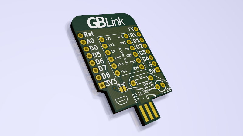
This is a shield to connect your Game Boy Pocket/Light/Color to a Wemos D1 Mini, a tiny ESP8266 board, or an MH-ET LIVE MiniKit, an ESP32 board that is pin-compatible with the D1 Mini.
The link cable connects directly to the PCB. The shield also has room for an optional resistor + 3mm LED combo. The LED will light up when a Game Boy is connected and powered on.
It can be used with a bunch of cool projects:
| Game Boy pin | D1 Mini pin | MiniKit pin |
|---|---|---|
| Ground | Ground | Ground |
| Vcc | D8 (optional, see note) | GPIO5 (optional, see note) |
| Serial Out | D7 | GPIO23 |
| Serial In | D6 | GPIO19 |
| Clock | D5 | GPIO18 |
| SD | Not connected | Not connected |
Vcc Note: you can optionally bridge the GB>D8 jumper on the shield. This will pull D8/GPIO5 high (3.3v) when a Game Boy is connected. This is not intended to power anything: it's just supposed to be a logic signal. Remember to set the pin to pulldown mode, or it will change state at random!
You can get this made for about $8 for three copies at OSHPark. Of course, any other PCB fab will also be able to make this. Make sure the PCB is 1.6mm thick so it fits in the Game Boy cable.
Since this is just a PCB, you will need some extra components to make it work.
The Game Boy runs at 5V, but both the ESP8266 and the ESP32 use 3.3V. You will need a level shifter with the same footprint as the SparkFun Logic Level Converter.
Your ESP board might come with these, but you'll need two 8-pin male headers to solder/connect the shield to the microcontroller board. The SparkFun 10-Pin Header is a good example (you can just snip off two pins).
This board works with Game Boy Pocket/Light/Color link cables. You can find them for cheap on AliExpress, or for less cheap on Amazon. Just make sure you're not getting the Original Game Boy cable (sometimes called DMG) since it's not the same size and will not work with this shield.
You can use a 330 Ohm resistor and a 3mm LED.
| Qty | Value | Footprint | References |
|---|---|---|---|
| 2 | CONN_01X08 | D1_mini:D1_mini_Pin_Header | P1, P2 |
| 1 | 1KOHM-HORIZ-1_4W-1% | Resistors:AXIAL-0.3 | R1 |
| 1 | LED3MM | LED:LED_3MM | D1 |
| 1 | LEVEL SHIFTER | Boards:SPARKFUN_LOGIC_LEVEL_CONVERTER | B1 |
| 1 | LOGO | Aesthetics:gblinksmall | G*** |
| 1 | OSHW | D1_mini:OSHW | |
| 1 | SolderJumper_2_Open | Jumper:SolderJumper-2_P1.3mm_Open_RoundedPad1.0x1.5mm | JP1 |
| 1 | gb-link-socket | gb-link-socket:gb-link-socket | GB1 |


FrameworkComputer/ExpansionCards
Reference designs and documentation to create Expansion Cards for the Framework Laptop

VoronDesign/Voron-Hardware
Cool Hardware designed by the Voron Design group

hackclub/OnBoard
💡 Join 1,000 teenagers and make your first PCB with a $100 grant!


adamws/kicad-kbplacer
KiCad plugin for automatic keyboard's key placement and routing
It measures 25.7 × 40.9 mm and has 2 copper layers, 1.6 mm thick.
9 parts. The full list of its parts is on this page, with links to each part's symbol and footprint where PCBKit's library has them.
From the iamjackg/d1mini-gb-shield repository on GitHub, at the commit this page was made from: the board is d1mini-gb.kicad_pcb. PCBKit opens the board in the browser, with nothing to install.
Its repository states no licence, so its author keeps all rights: ask iamjackg before reusing the design.