2 layers158 × 11 mm
Daylight Matchstick
VoronDesign/Voron-Hardware
Cool Hardware designed by the Voron Design group
22 parts1.1kGPL-3.0

 ia31/mini-piano-pcb
A five-key electronic piano designed in KiCad for Rice University's ELEC 240. An LMC555 runs in astable mode, and each key selects a different timing resistance, setting the frequency of the square wave that drives a…
PCB Design is an open-source printed circuit board by ia31, from the ia31/mini-piano-pcb repository on GitHub. It is a 2-layer board of 50 × 50.5 mm with 22 parts on 14 nets, routed with 101 tracks and 0 vias.
Its parts include 8 resistors, 5 switches, 4 capacitors, 2 diodes and 1 IC.
A five-key electronic piano designed in KiCad for Rice University's ELEC 240. An LMC555 runs in astable mode, and each key selects a different timing resistance, setting the frequency of the square wave that drives a piezo buzzer.
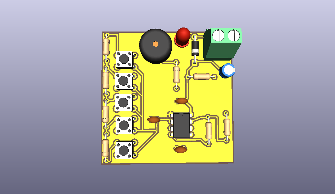
Front copper (PDF) · Back copper (PDF) · Board outline (PDF)
Instead of giving each key its own resistor, R2 through R6 form a single series ladder, and each key taps a different point on it. Each note's R_B is the running sum of the resistors above its tap:
| Note | Key | R_B | Theoretical f | Target |
|---|---|---|---|---|
| A5 | SW1 | 5.6k | 907 Hz | 880 Hz |
| G5 | SW2 | 6.6k | 806 Hz | 784 Hz |
| E5 | SW3 | 8.4k | 671 Hz | 659 Hz |
| D5 | SW4 | 9.6k | 604 Hz | 587 Hz |
| C5 | SW5 | 11.1k | 536 Hz | 523 Hz |
With f = 1 / (ln2 * (R_A + 2R_B) * C), R_A = 4.7k, and C = 100 nF.
What this buys:
Every note comes out 30 to 53 cents sharp in theory. Because the error is roughly uniform, the whole scale can be pulled down together with one part change: adding about 2.2 nF in parallel with C1 lowers every note by roughly the same amount.
The design is complete. I'm soldering and testing the board this semester, and I'll add photos and measured frequencies once it's built.
| Qty | Value | Footprint | References |
|---|---|---|---|
| 3 | 1k | Resistor_THT:R_Axial_DIN0207_L6.3mm_D2.5mm_P10.16mm_Horizontal | R3, R7, R8 |
| 1 | 1.2k | Resistor_THT:R_Axial_DIN0207_L6.3mm_D2.5mm_P10.16mm_Horizontal | R5 |
| 1 | 1.5k | Resistor_THT:R_Axial_DIN0207_L6.3mm_D2.5mm_P10.16mm_Horizontal | R6 |
| 1 | 1.8k | Resistor_THT:R_Axial_DIN0207_L6.3mm_D2.5mm_P10.16mm_Horizontal | R4 |
| 1 | 10 nF | Capacitor_THT:C_Disc_D5.0mm_W2.5mm_P2.50mm | C3 |
| 1 | 100 nF | Capacitor_THT:C_Disc_D5.0mm_W2.5mm_P2.50mm | C1 |
| 1 | 100nF | Capacitor_THT:C_Disc_D5.0mm_W2.5mm_P2.50mm | C2 |
| 1 | 10uF | Capacitor_THT:CP_Radial_D5.0mm_P2.00mm | C4 |
| 1 | 1N5817 | Diode_THT:D_DO-41_SOD81_P10.16mm_Horizontal | D3 |
| 1 | 4.7k | Resistor_THT:R_Axial_DIN0207_L6.3mm_D2.5mm_P10.16mm_Horizontal | R1 |
| 1 | 5.6k | Resistor_THT:R_Axial_DIN0207_L6.3mm_D2.5mm_P10.16mm_Horizontal | R2 |
| 1 | A5 | Button_Switch_THT:SW_PUSH_6mm | SW1 |
| 1 | C5 | Button_Switch_THT:SW_PUSH_6mm | SW5 |
| 1 | D5 | Button_Switch_THT:SW_PUSH_6mm | SW4 |
| 1 | E5 | Button_Switch_THT:SW_PUSH_6mm | SW3 |
| 1 | G5 | Button_Switch_THT:SW_PUSH_6mm | SW2 |
| 1 | LED | LED_THT:LED_D5.0mm | D2 |
| 1 | LMC555xN | Package_DIP:DIP-8_W7.62mm | U1 |
| 1 | Screw_Terminal_01x02 | TerminalBlock_Phoenix:TerminalBlock_Phoenix_MKDS-1,5-2-5.08_1x02_P5.08mm_Horizontal | J1 |
| 1 | piezo | Buzzer_Beeper:Buzzer_TDK_PS1240P02BT_D12.2mm_H6.5mm | BZ1 |
VoronDesign/Voron-Hardware
Cool Hardware designed by the Voron Design group

hoglet67/RGBtoHDMI
Bare-metal Raspberry Pi project that provides pixel-perfect sampling of Retro Computer RGB/YUV video and conversion to HDMI

hackclub/OnBoard
💡 Join 1,000 teenagers and make your first PCB with a $100 grant!

abhishek-kakkar/BeagleLogic
A Software Suite that implements a logic analyzer with the PRU on the BeagleBone / BeagleBone Black.

Chrismettal/flipper-zero-backpacks
Backpack-style addon boards for the Flipper Zero!


CRImier/MyKiCad
My KiCad boards. Can't be bothered uploading individually anymore, so here you go.
It measures 50 × 50.5 mm and has 2 copper layers, 1.6 mm thick.
22 parts. The full list of its parts is on this page, with links to each part's symbol and footprint where PCBKit's library has them.
From the ia31/mini-piano-pcb repository on GitHub, at the commit this page was made from: the board is PCB Design.kicad_pcb and its schematic PCB Design.kicad_sch. PCBKit opens the board in the browser, with nothing to install.
Its repository states no licence, so its author keeps all rights: ask ia31 before reusing the design.