4 layers34 × 48 mm

 https-shubhamsahu/niva
Live dashboard · Firmware · Rev C.1 hardware · Scoring rules
NIVA insole R is an open-source printed circuit board by https-shubhamsahu, from the https-shubhamsahu/niva repository on GitHub. It is a 2-layer board of 217.5 × 234 mm with 8 parts on 9 nets, routed with 117 tracks and 8 vias.
Its parts include 2 connectors and 1 resistor.
Live dashboard · Firmware · Rev C.1 hardware · Scoring rules
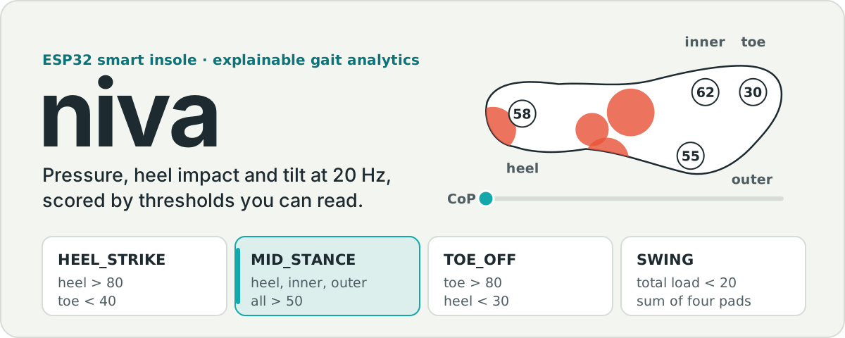
Niva is a smart insole for gait screening. An ESP32 reads four force pads, a piezo disc under the heel and an MPU6050, then streams 20 frames a second to a React dashboard and a Flutter app. Each gait phase, score and alert comes from a threshold in one TypeScript file, so you can point at the exact reading that set off an alert. Niva was shown at Automation Expo in July 2026.
Status: the bench build runs today. The Rev C.1 wearable pod is designed, routed and DRC-clean in KiCad, but it hasn't been built or measured yet. Niva is a research and screening prototype. It isn't a medical device.
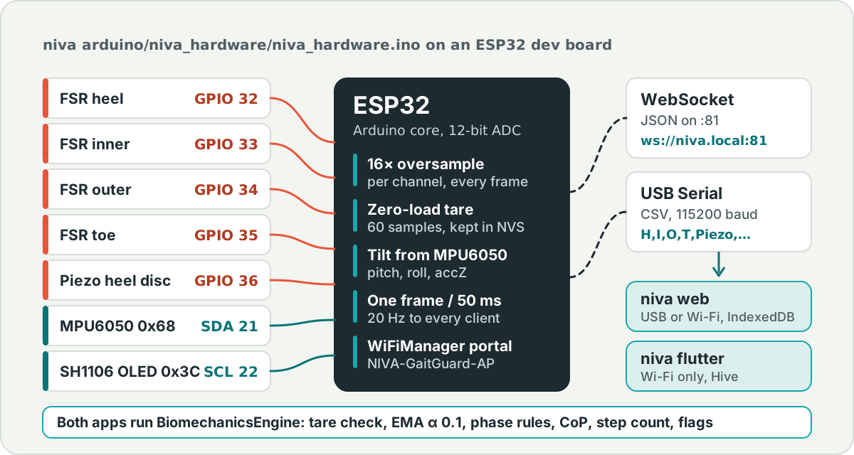
The active sketch is niva arduino/niva_hardware/niva_hardware.ino.
| Signal | ESP32 pin | Notes |
|---|---|---|
| FSR heel | GPIO 32 | ADC1_CH4 |
| FSR inner (1st metatarsal) | GPIO 33 | ADC1_CH5 |
| FSR outer (5th metatarsal) | GPIO 34 | ADC1_CH6 |
| FSR toe | GPIO 35 | ADC1_CH7 |
| Piezo heel disc | GPIO 36 | ADC1_CH0, the impact channel |
| I2C SDA | GPIO 21 | MPU6050 at 0x68, SH1106 OLED at 0x3C |
| I2C SCL | GPIO 22 | shared bus |
| Status LED | GPIO 2 | blinks during tare |
What the firmware does each frame:
calibrate or tare over WebSocket or Serial)You set up Wi-Fi through a WiFiManager captive portal (NIVA-GaitGuard-AP), and the board answers at ws://niva.local:81 over mDNS.
JSON over WebSocket (ws://<esp32-ip>:81):
{"heel":42.00,"inner":68.00,"outer":31.00,"toe":27.00,"piezo":176.00,"pitch":-2.40,"roll":1.30,"accZ":9.72}CSV over USB Serial at 115200 baud:
H,I,O,T,Piezo,Pitch,Roll,AccZThe simpler sketch, esp32_gaitguard_wifi_manager, uses hardcoded Wi-Fi credentials and doesn't drive the IMU or the OLED. BLE isn't in any sketch, and the IMU in firmware is the MPU6050 (you won't find BMI270 code here).
Both apps run the same engine on every frame: biomechanicsEngine.ts in the web app and biomechanics_engine.dart in Flutter, and there's no trained model in it. Here are the rules, with the default values from the code, so you can check any number on the dashboard by hand:
| Output | Rule |
|---|---|
| Tare check | The first 30 frames must be steady: load range 8 or less, mean load 55 or less, tilt 7 or less, impact 60 or less. After 60 frames it carries on without a baseline. |
| Smoothing | EMA with α = 0.1, a deadband of 2.5 on pressure and 0.8 on angles |
| Contact | stance while the filtered total is above 45 |
| Step | piezo above 200, heel above 80, heel rising by more than 8, and the foot was in swing |
| Cadence | 60 divided by the time between heel strikes (0.2 s to 3 s) |
| Phase | HEEL_STRIKE heel > 80 and toe < 40; MID_STANCE heel, inner and outer > 50; TOE_OFF toe > 80 and heel < 30; SWING total < 20 |
| Centre of pressure | load-weighted average of the four pad positions |
| Stability score | 100 - 9 × tilt - 30 × impact level, clamped to 0 to 100 |
| Flags | supination risk when roll > 8 and outer > inner; heel-dominant gait when the heel carries over 70 % of the load for 5 frames; high sway when tilt reaches 6; ischemic pressure risk when the static-load integral passes 50 |
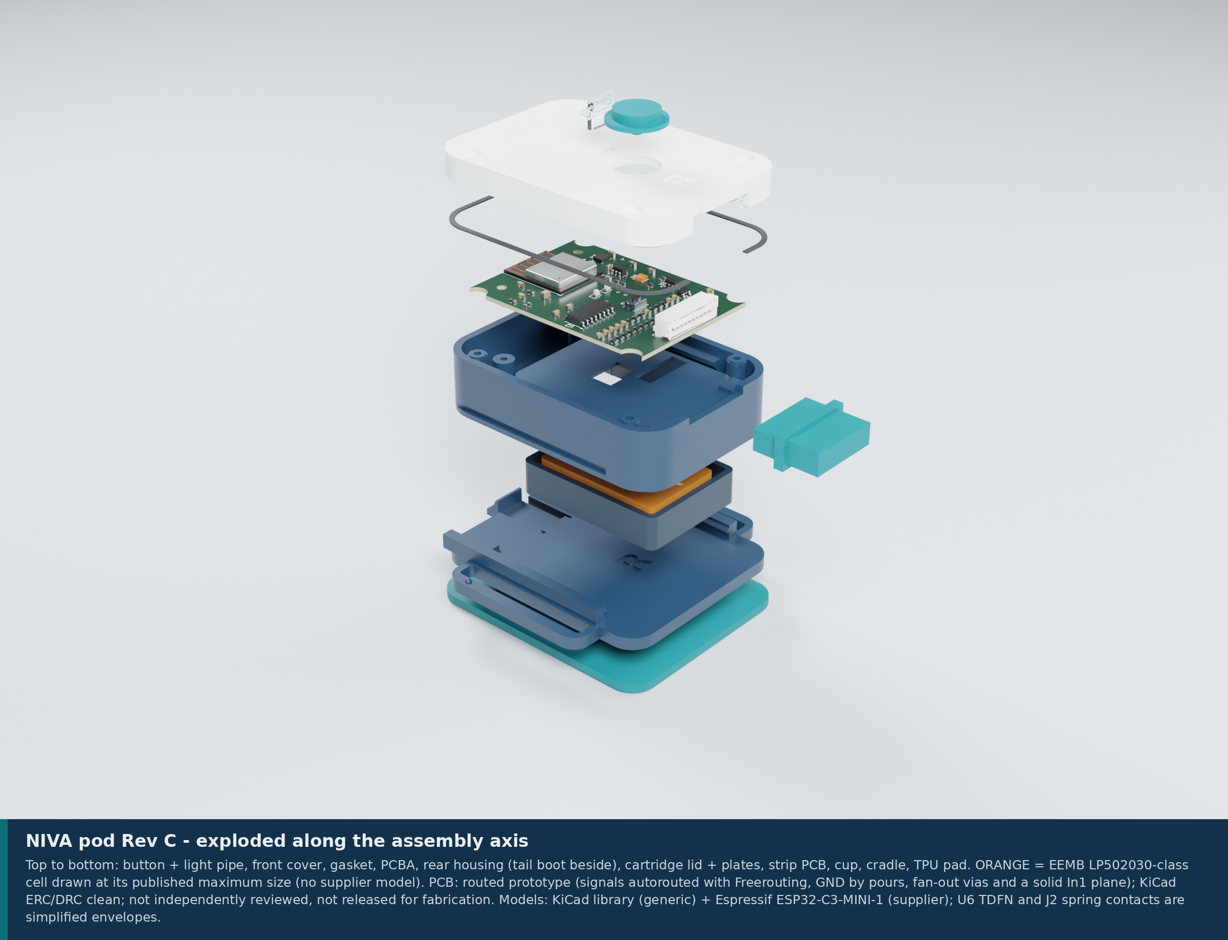
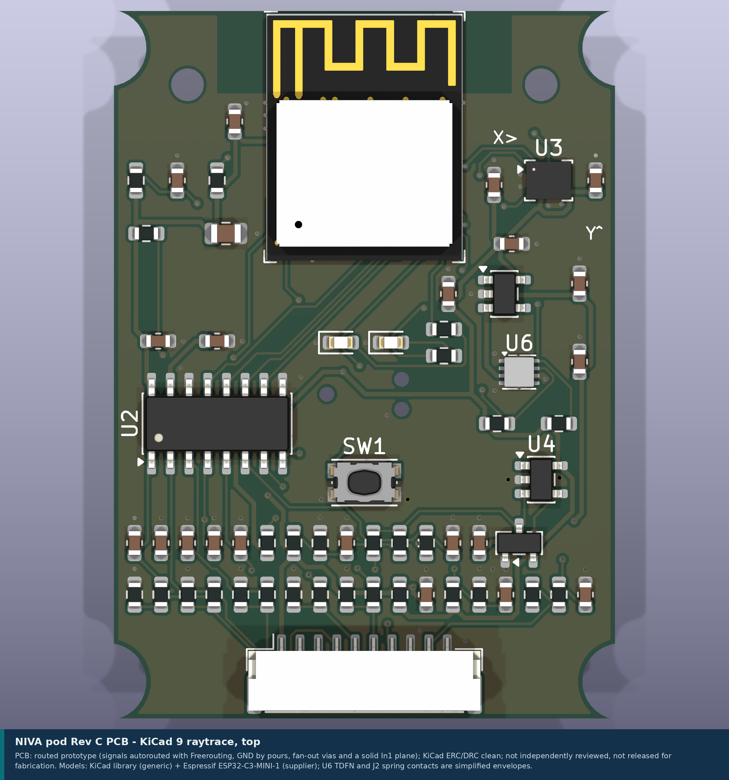
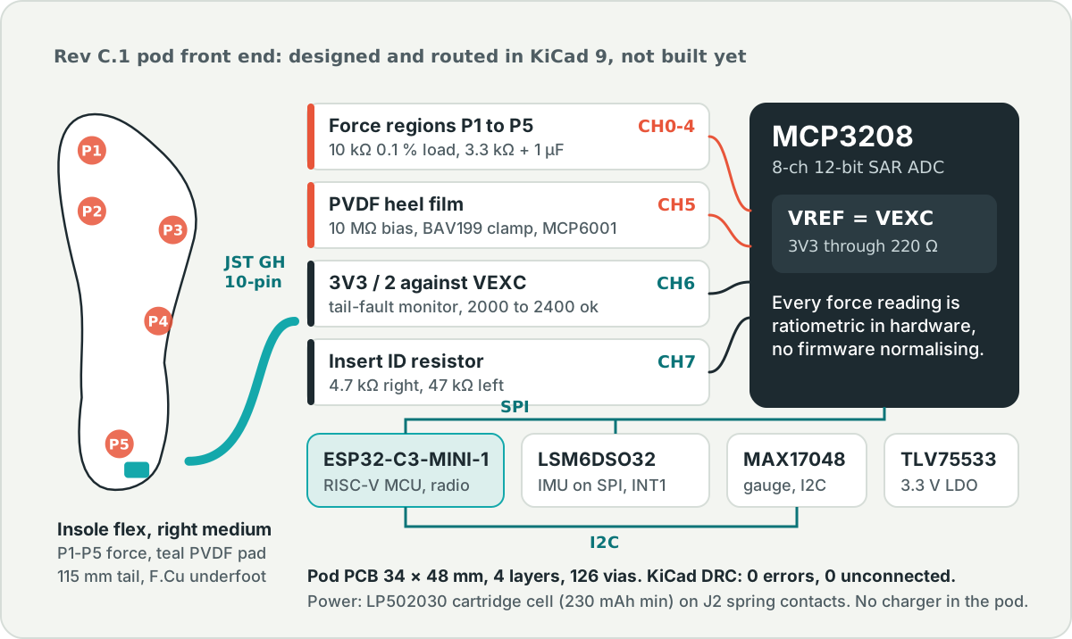
The next build swaps the dev board for a pod you wear on the lower shin: ESP32-C3, an MCP3208 ADC, an LSM6DSO32 IMU, a removable battery cartridge, one button and one light. A desk dock charges the cartridges. Every part comes out of a script (FreeCAD 1.1, KiCad 9, Blender 4.5), so you can rebuild the whole design from hardware/work/.
 |  |
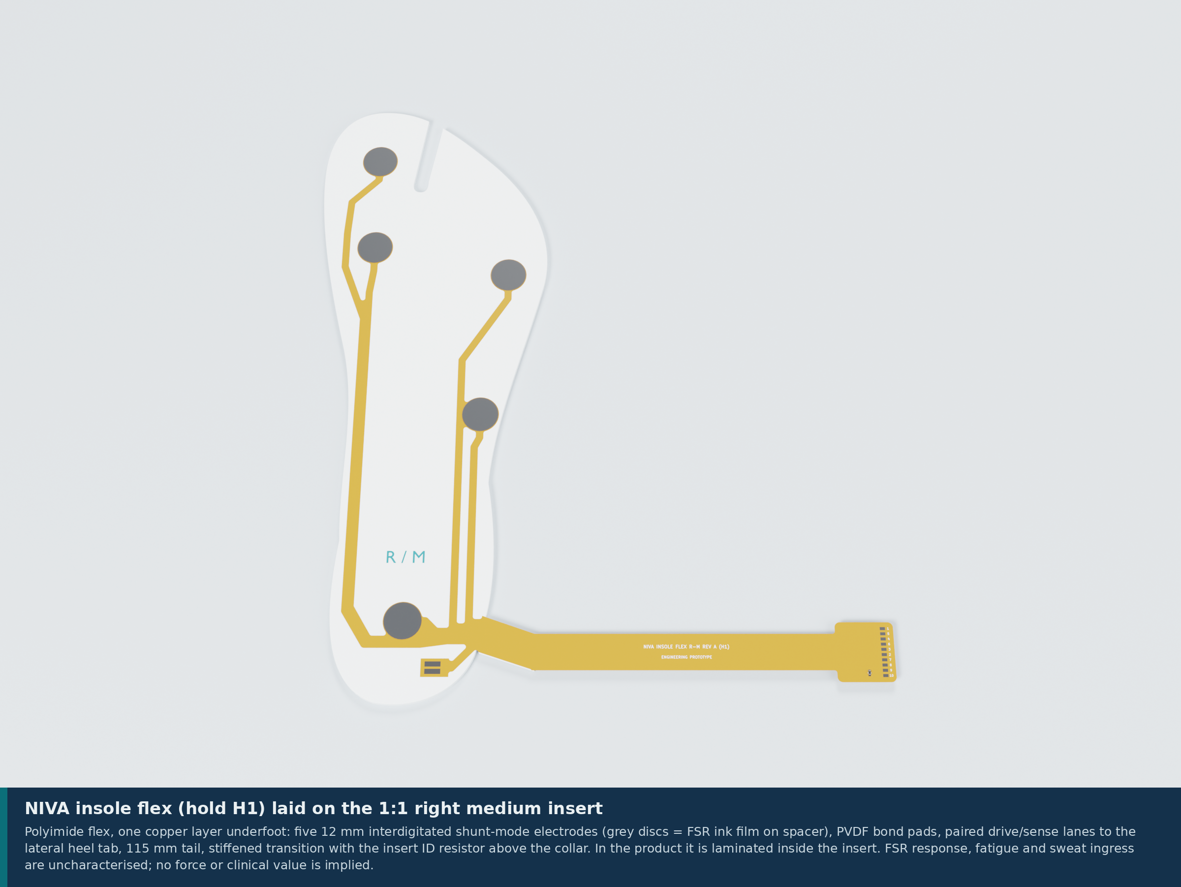 | 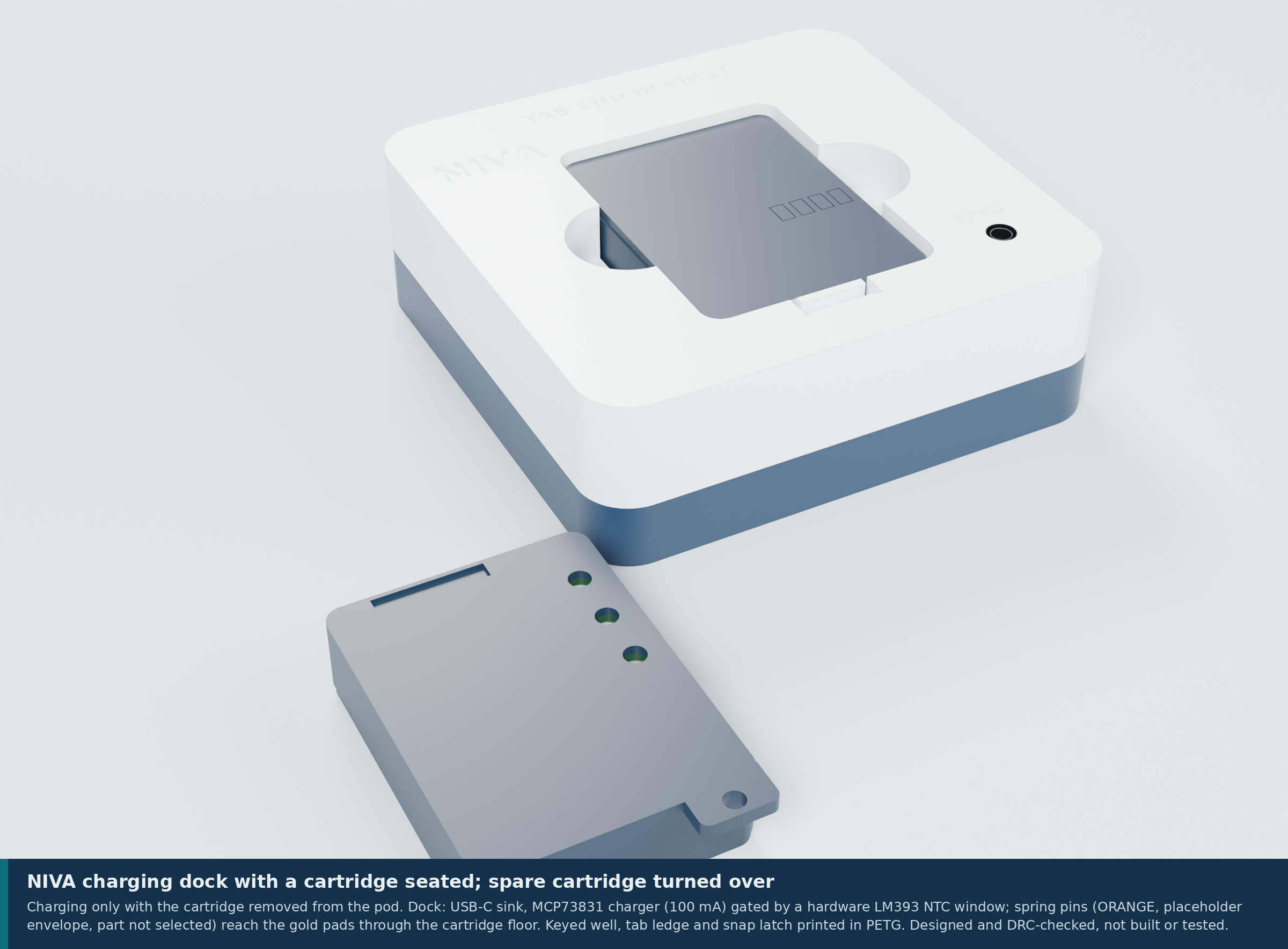 |
These are CAD renders, not photos. The signal chain inside the pod:
| Board | Size and layers | Routing | KiCad ERC / DRC |
|---|---|---|---|
| Pod | 34 × 48 × 1.0 mm, 4 layers, In1 = GND plane | GND fan-out, Freerouting signals, pours; 547 segments, 126 vias | ERC 0 errors; DRC 0 errors, 0 unconnected |
| Cartridge strip | 3.4 × 30 × 0.8 mm, 2 layers | hand-routed | 0 / 0 |
| Dock | 58 × 56 × 1.6 mm, 2 layers | Freerouting and GND pours | 0 / 0 |
| Insole flex R and L | 0.12 mm polyimide, F.Cu only underfoot | generated paired lanes | 0 / 0 |
What's still open: nothing has been printed, built, powered or measured. RF, sealing, skin contact, cleaning and FSR characterisation are untested, and nobody outside the project has reviewed the design. A clean ERC and DRC is an automated check. It isn't a design review. The pod has a bare-PCB first-article Gerber set for bench bring-up; the rest are review-only. The full list is in VERIFICATION-PLAN.md and the hardware README.
Don't have the hardware? Open the live dashboard and switch to Simulation. It streams generated gait for six modes (Normal, Parkinson, Stroke, Neuropathy, Foot Drop, Ataxia) through the same engine. The simulated patterns are synthetic, so don't read them as patient data.
Install only what you need for the part you're running:
niva web)cd "niva web"
npm install
# if peer dependency conflicts appear:
npm install --legacy-peer-deps
npm run devOther scripts:
npm run build
npm run preview
npm run lint
Optional environment file, niva web/.env.local:
VITE_ESP32_WS_URL=ws://<esp32-ip>:81
VITE_ESP32_WS_RELAY_URL=wss://<your-relay-domain>/ws
VITE_ESP32_WS_RELAY_TARGET_KEY=target
VITE_DATASET_UPLOAD_URL=https://your-api.example.com/upload
VITE_DATASET_UPLOAD_TOKEN=your_optional_bearer_token
Optional WebSocket relay, needed when an HTTPS dashboard has to reach a ws:// ESP32:
cd "niva web/relay"
npm install
npm startniva flutter)cd "niva flutter"
flutter pub get
flutter analyze
flutter test
flutter runThe ESP32 endpoint, relay URL and upload URL are runtime settings on the Device tab, not build-time env files.
niva arduino)Open a sketch in Arduino IDE, install the libraries listed in niva arduino/README.md (WiFiManager, WebSockets, U8g2), select an ESP32 board and upload:
niva arduino/niva_hardware/niva_hardware.inoniva arduino/esp32_gaitguard_wifi_manager/esp32_gaitguard_wifi_manager.inoOpen Serial Monitor at 115200 baud, note the printed IP, and point the Flutter Device tab or the web Settings page at ws://<ESP32_IP>:81.
web_socket_channel, fl_chartws.github/workflows/deploy-pages.yml, which builds niva webThere's no application server or database. Your datasets stay in your browser (IndexedDB) or on your phone (Hive). CSV upload to an external research API is optional.
| Directory | Contents |
|---|---|
niva arduino/ | ESP32 firmware: ADC acquisition, tare, IMU, OLED, Wi-Fi and WebSocket |
niva web/ | Clinician dashboard, biomechanics views, dataset export and upload, WebSocket relay |
niva flutter/ | Patient-facing app: dashboard, device pairing over WebSocket, insights, trends, CSV export |
hardware/ | Rev C.1 prototype: FreeCAD pod and dock, KiCad 9 pod, cartridge, dock and insole flex, verification plan, Blender scenes. Not reviewed or released for fabrication. |
docs/brand/ | Logo source files |
SIH2026-DECK-KIT/ | Smart India Hackathon 2026 deck pipeline (HTML slides rendered to PDF) |
assets/readme/, scripts/ | README diagrams and the script that builds them from the insole template |
| File | Contents |
|---|---|
niva arduino/README.md | Sketches, pin map, libraries |
niva web/README.md | Dashboard setup, telemetry formats, Pages deploy |
niva web/JUDGES_WALKTHROUGH.md | Algorithm and data walkthrough |
niva flutter/README.md | Flutter setup, architecture, run commands |
niva flutter/DESIGN.md | Flutter design notes |
niva flutter/BACKEND_LOGIC.md | Data contract and storage |
hardware/outputs/NIVA-3D-engineering-prototype/README.md | Rev C.1 boards, CAD, renders, open items |
Niva is an engineering and research screening tool. It is not a medical diagnosis device.
| Qty | Value | Footprint | References |
|---|---|---|---|
| 1 | 4.7k 0.1% | Resistor_SMD:R_0603_1608Metric | R1 |
| 1 | CABLE TO POD J1 (JST GH 10) | NIVA_insole:WirePads_1x10_P2.0mm_LaneOrder | J1 |
| 1 | P1 Big toe (shunt FSR, 12 mm) | NIVA_insole:FSR_Interdigitated_D12mm | FSR1 |
| 1 | P2 Medial forefoot (shunt FSR, 12 mm) | NIVA_insole:FSR_Interdigitated_D12mm | FSR2 |
| 1 | P3 Lateral forefoot (shunt FSR, 12 mm) | NIVA_insole:FSR_Interdigitated_D12mm | FSR3 |
| 1 | P4 Lateral midfoot (shunt FSR, 12 mm) | NIVA_insole:FSR_Interdigitated_D12mm | FSR4 |
| 1 | P5 Heel (shunt FSR, 12 mm) | NIVA_insole:FSR_Interdigitated_D12mm | FSR5 |
| 1 | V1 PVDF FILM (signal, return) | NIVA_insole:PVDF_BondPads_2x6x2mm | J2 |
It measures 217.5 × 234 mm and has 2 copper layers, 0.12 mm thick.
8 parts. The full list of its parts is on this page, with links to each part's symbol and footprint where PCBKit's library has them.
From the https-shubhamsahu/niva repository on GitHub, at the commit this page was made from: the board is hardware/outputs/NIVA-3D-engineering-prototype/electronics/insole/NIVA-insole-R.kicad_pcb and its schematic hardware/outputs/NIVA-3D-engineering-prototype/electronics/NIVA-controller.kicad_sch. PCBKit opens the board in the browser, with nothing to install.
Its repository states no licence, so its author keeps all rights: ask https-shubhamsahu before reusing the design.


https-shubhamsahu/niva
Live dashboard · Firmware · Rev C.1 hardware · Scoring rules

https-shubhamsahu/niva
Live dashboard · Firmware · Rev C.1 hardware · Scoring rules


joeycastillo/Sensor-Watch
A board replacement for the classic Casio F-91W wristwatch

rusefi/rusefi
rusefi - GPL internal combustion engine control unit

hoglet67/RGBtoHDMI
Bare-metal Raspberry Pi project that provides pixel-perfect sampling of Retro Computer RGB/YUV video and conversion to HDMI

shanteacontrols/OpenDeck
A platform for building interactive control and sensing devices using MIDI and OSC built with Zephyr RTOS.

hackclub/OnBoard
💡 Join 1,000 teenagers and make your first PCB with a $100 grant!

dangiu/PicoMemcard
Emulating PSX Memory Card (or controller) using a Raspberry Pi Pico

OLIMEX/DIY-LAPTOP
Do It Yourself Open Source Hardware and Software Modular Hacker's Friendly Laptop