2 layers20.5 × 24.8 mm
 hpvdt/timer_tutorial
Introductory project for new electronics members
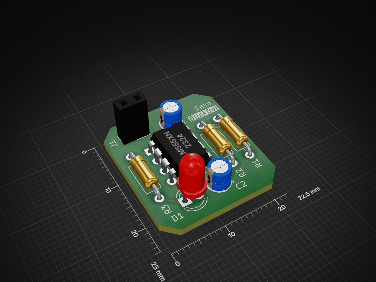
Timer tutoiral is an open-source printed circuit board by hpvdt, from the hpvdt/timer_tutorial repository on GitHub. It is a 2-layer board of 22.5 × 25 mm with 8 parts on 7 nets, routed with 13 tracks and 1 via.
Its parts include 3 resistors, 2 capacitors, 1 IC, 1 diode and 1 connector.
This is a 555 timer based project for new electronics team members to wet their feet in the world of hardware design and prototyping, without needing to do any coding!
The goal is simple, have new members design an LED blinker using a 555-timer chip to flash at about 0.5 Hz. Ideally they start by reading and digesting the datasheet for the 555 timer (included as a PDF in this repository) and working their way to a circuit board in KiCad with some prototyping inbetween so they get experience with all stages of a circuit bring up.
In addition to the 555 datasheet, a complete KiCad project for this project is also included. New members should make their own projects from scratch as part of this exercise but this can be distributed to late joiners or used as a reference when lecturing about KiCad.
New members shouldn't really be expected to prepare for this project (at least for the first (prototyping) part). All prototyping materials should be prepared by the head of electronics in advance. Luckily nothing is needed for this that isn't usually laying around McCaul already, except for perhaps some 555 chips.
For teaching/learning KiCad it is helpful for each member to have their own laptop with the latest version of KiCad pre-installed so they can follow along instead of just watching. This can easily be "homework" if the project is borken between multiple sessions.
The task for this project is simple, create a blinker that could be used as an indicating light for when a bike needs to turn. Just like with a car, the blinking needs to be perceptible so neither too fast nor too slow, roughly a second of the LED being on followed by a second of it being off is adequate.
To accomplish this we are going to use a 555 timer chip, arguably the most produced integrated circuit (IC) ever and a common gateway chip to hobby electronics. It can be used many different ways so one must read the documentation on the chip in the form a datasheet and then determine how to proceed with the design.
Once familiar with the chip and a rough design is settled on, we can embark on the rest of the electronics design process! Ideally with a nice flashy prototype by the end of it.
This project is meant to be reflective of the general electronics development process. In general the following steps are completed in roughly this order, not too disimilar to the flow of a majority of engineering projects:
Going through all these steps in a single session, especially when starting out is unlikely without it feeling rushed or a marathon of a session. Consider doing the prototyping in one large session with a shorter follow-up session for the EDA portion, this also gives them time to install KiCad at home in advance of the KiCad session. (Protip: it is much easier when teaching larger groups to have everyone at a similar stage in the process.)
| Qty | Value | Footprint | References |
|---|---|---|---|
| 1 | 10u | Capacitor_THT:CP_Radial_D4.0mm_P2.00mm | C2 |
| 1 | 144k | Resistor_THT:R_Axial_DIN0207_L6.3mm_D2.5mm_P10.16mm_Horizontal | R2 |
| 1 | 1k | Resistor_THT:R_Axial_DIN0207_L6.3mm_D2.5mm_P10.16mm_Horizontal | R1 |
| 1 | 1u | Capacitor_THT:CP_Radial_D4.0mm_P2.00mm | C1 |
| 1 | 470 | Resistor_THT:R_Axial_DIN0207_L6.3mm_D2.5mm_P10.16mm_Horizontal | R3 |
| 1 | LED | LED_THT:LED_D4.0mm | D1 |
| 1 | LM555xN | Package_DIP:DIP-8_W7.62mm | U1 |
| 1 | PWR | Connector_PinSocket_2.54mm:PinSocket_1x02_P2.54mm_Vertical | J1 |
It measures 22.5 × 25 mm and has 2 copper layers, 1.6 mm thick.
8 parts. The full list of its parts is on this page, with links to each part's symbol and footprint where PCBKit's library has them.
From the hpvdt/timer_tutorial repository on GitHub, at the commit this page was made from: the board is timer_tutoiral.kicad_pcb and its schematic timer_tutoiral.kicad_sch. PCBKit opens the board in the browser, with nothing to install.
Its repository states no licence, so its author keeps all rights: ask hpvdt before reusing the design.

joeycastillo/Sensor-Watch
A board replacement for the classic Casio F-91W wristwatch

rusefi/rusefi
rusefi - GPL internal combustion engine control unit

hoglet67/RGBtoHDMI
Bare-metal Raspberry Pi project that provides pixel-perfect sampling of Retro Computer RGB/YUV video and conversion to HDMI

shanteacontrols/OpenDeck
A platform for building interactive control and sensing devices using MIDI and OSC built with Zephyr RTOS.

hackclub/OnBoard
💡 Join 1,000 teenagers and make your first PCB with a $100 grant!

dangiu/PicoMemcard
Emulating PSX Memory Card (or controller) using a Raspberry Pi Pico

OLIMEX/DIY-LAPTOP
Do It Yourself Open Source Hardware and Software Modular Hacker's Friendly Laptop