4 layers297.5 × 187.5 mm

 howie-j/opensolder55
Fully open source JBC T245-compatible soldering station
Opensolder is an open-source printed circuit board by howie-j, from the howie-j/opensolder repository on GitHub, published under the GPL-3.0 licence. It is a 2-layer board of 100 × 44 mm with 69 parts on 53 nets, routed with 549 tracks and 288 vias.
It is built around the SI8751-KIT, PDSE1-S24-S5-S and MAX4238ASA, with the PCT2075GVX, VOS628AT and KIA50N06BD among its other parts. Its parts include 21 capacitors, 20 resistors, 8 ICs, 5 connectors and 3 diodes. It belongs with the STM32 boards of this library.


Fully open source JBC T245-compatible soldering station and tool holder
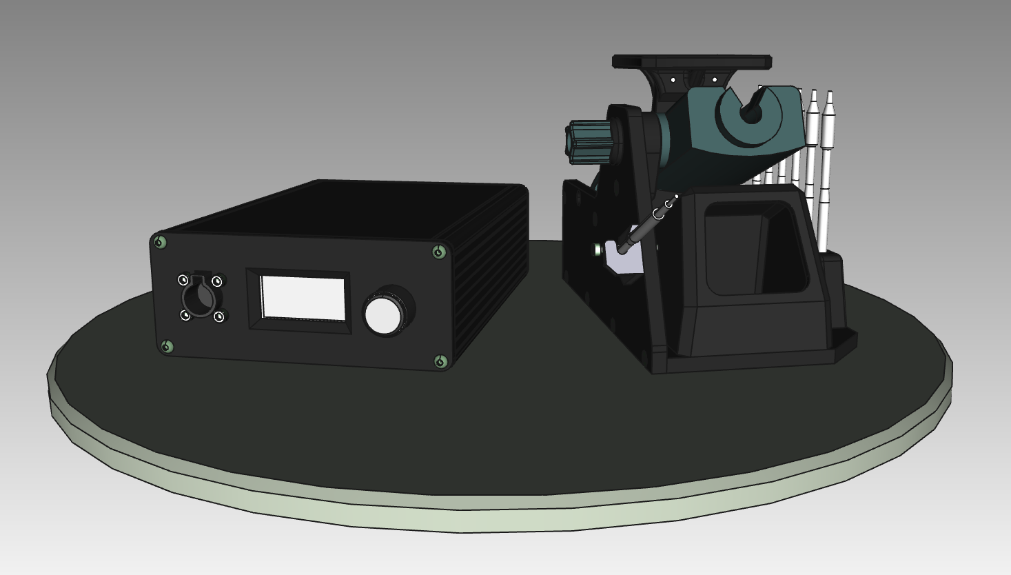
When my cheap T12 clone soldering station went up in smoke, I started looking into either buying a JBC CDB, or building a proper soldering station. The internet is already crowded with DIY JBC compatible stations, but most are poorly documented, or does not have the quality-of-life features that the original have.
The unisolder project is very impressive, but way to complex and "universal" for my needs. Marco Reps built a cool C470 station that i liked the simplicity of, and this project is highly inspired by that.

The station is built in a Hammond enclosure, with a center mounted transformer. The PCB is mounted to the custom front panel, and all 230VAC connections is in the rear of the chassis.
There is two connectors on the rear panel, one for connecting to the stand, and an optional ST-link connector for firmware upgrades.

The stand is made of 3D-printed parts, a genuine JBC tool holder, a tip remover made from aluminium angle and some fasteners. Most parts can be made from aluminium sheet if that is preferred.
This is the internal connections of the JBC C245 cartridge:

The schematic is divided into three sheets: AC, Analog and MCU.
The 24VAC input is fused, then connected directly to the tip center pin (5). Switching is done with two N-channel mosfets, driven by a Si8751 isolated gate driver.
Zero cross detection is done with an AC optocoupler, and the current is limited by three 10k resistors (to reduce BOM items). This solution triggers the ZeroCross about 90uS prematurely, and that is compensated for in firmware.
The MCU and thermocouple frontend must be electrically isolated, and a 24V to 5V DCDC PSU module solves that problem. The DCDC-supply is preregulated with a 24V linear regulator, and post-regulated to 3.3V with a LDO. This power supply chain is in need of some simplification, but the components are few and cheap, and it works great for now.
The thermocouple signal is amplified with a MAX4238 chopper opamp, with a fairly arbitrary amplification of 221, since temperature calibration is done in firmware anyway. No negative supply rail means the thermocouple can't sense lower temperatures than room temp, but that's not needed for a soldering station.
Long handpiece wires means lots of crosstalk, so a pair of diodes clamps the thermocouple input at Vf. The MCU pin TIP_CLAMP is driven low when power is applied to the handpiece, to clamp noise on the opamp input. When its time to measure tip temperature, the pin is set to input, and a delay waits for the RC filter to stabilize.
To sense if there is a tip cartridge in the handpiece, TIP_CHECK is driven high. The low impedance of the thermocouple + heater (a few Ω's) will create a very low voltage drop. If the tip is removed, the Vf of the input protection diode will drive THERMOCOUPLE_ADC close to 3.3V.
A STM32F072 is used since I have a few of them in stock, but almost any STM32 could be adapted to work. To sense PCB temperature (and for cold junction compensation), an I2C temp sensor is added. The MCU might have an internal temperature sensor, but have not looked into that yet.
The rotary encoder and handpiece stand inputs are filtered using plain RC filters. This, combined with the input hysteresis, removes most input noise. The TIM encoder inputs also have additional filtering and FSM redundancy.
Check out this interactive BOM


The PCB is quite low density, uses 0805 SMD components and is fully hand solderable with a microscope. Connections to the rear connectors (stand and ST-link) is done via a 6-pin IDC connector, so no crimping of tiny connector pins are necessary. The PCB is mounted to the front panel via the rotary encoder and the handpiece connector.
The firmware is simple and functional, and uses a modified hysteresis temperature controller that is very fast but has some initial overshoot. Currently all default values are set in opensolder.h, and are reset when the station is powered off.
Nothing is currently missing for regular functionality. However some features would be cool to have:
The unisolder project
Marco Reps
foldvarid93's JBC Soldering Station
johnmx's eevblog thread
| Qty | Value | Footprint | References |
|---|---|---|---|
| 10 | 100n | Capacitor_SMD:C_0805_2012Metric | C5, C8, C12, C13, C14, C15, C16, C17, C18, C19 |
| 10 | 10k | Resistor_SMD:R_0805_2012Metric | R1, R2, R3, R4, R5, R9, R11, R13, R15, R17 |
| 5 | 100k | Resistor_SMD:R_0805_2012Metric | R10, R12, R14, R16, R18 |
| 5 | 1u | Capacitor_SMD:C_1210_3225Metric | C2, C3, C4, C6, C11 |
| 3 | 10n | Capacitor_SMD:C_0805_2012Metric | C7, C20, C21 |
| 2 | 20p | Capacitor_SMD:C_0805_2012Metric | C9, C10 |
| 2 | 3k3 | Resistor_SMD:R_0805_2012Metric | R19, R20 |
| 2 | KIA50N06BD | Package_TO_SOT_SMD:TO-252-2 | Q1, Q2 |
| 2 | S1M | Diode_SMD:D_SMA | D2, D3 |
| 1 | +24V | TestPoint:TestPoint_Pad_D1.0mm | TP2 |
| 1 | +3V3 | TestPoint:TestPoint_Pad_D1.0mm | TP5 |
| 1 | +5V | TestPoint:TestPoint_Pad_D1.0mm | TP4 |
| 1 | 100 | Resistor_SMD:R_0805_2012Metric | R7 |
| 1 | 22k | Resistor_SMD:R_0805_2012Metric | R6 |
| 1 | 390 | Resistor_SMD:R_0805_2012Metric | R8 |
| 1 | 47u | Capacitor_THT:CP_Radial_D8.0mm_P3.50mm | C1 |
| 1 | AC_Input | Connector_Phoenix_MSTB:PhoenixContact_MSTBVA_2,5_3-G_1x03_P5.00mm_Vertical | J1 |
| 1 | AP2111H-3.3 | Package_TO_SOT_SMD:SOT-223 | U4 |
| 1 | Crystal_8MHz | Crystal:Crystal_SMD_HC49-SD | Y1 |
| 1 | Fast 12A | Fuse:Fuseholder_Cylinder-5x20mm_Schurter_0031_8201_Horizontal_Open | F1 |
| 1 | Heater | TestPoint:TestPoint_Pad_D1.0mm | TP3 |
| 1 | Hirose RPC1-12RB-6P(71) | 0_Howie:Hirose_RPC1 | J2 |
| 1 | L78L24_SOT89 | Package_TO_SOT_SMD:SOT-89-3 | U2 |
| 1 | MAX4238ASA | Package_SO:SOIC-8_3.9x4.9mm_P1.27mm | U5 |
| 1 | MB6S-TP | Package_TO_SOT_SMD:TO-269AA | D1 |
| 1 | OLED | 0_Howie:OLED_SSD1306_SPI_1.54 | U6 |
| 1 | PCT2075GV | Package_SO:TSOP-6_1.65x3.05mm_P0.95mm | U8 |
| 1 | PDSE1-S24-S5-S | 0_Howie:PDSE1_DCDC | PS1 |
| 1 | PEC11R-RotEnc | 0_Howie:RotaryEncoder_PEC11R_PEC12R | SW2 |
| 1 | Reset_Switch | Connector_PinSocket_2.54mm:PinSocket_1x02_P2.54mm_Vertical | J5 |
| 1 | STM32F072CBTx | Package_QFP:LQFP-48_7x7mm_P0.5mm | U7 |
| 1 | SWD | Connector_IDC:IDC-Header_2x03_P2.54mm_Vertical | J3 |
| 1 | Si8751 | Package_SO:SOIC-8_3.9x4.9mm_P1.27mm | U3 |
| 1 | UART | Connector_PinSocket_2.54mm:PinSocket_1x02_P2.54mm_Vertical | J4 |
| 1 | VOS628A | Package_SO:SOP-4_4.4x2.6mm_P1.27mm | U1 |
| 1 | ZeroCross | TestPoint:TestPoint_Pad_D1.0mm | TP1 |
The 68 most common of 69 parts.
It measures 100 × 44 mm and has 2 copper layers, 1.6 mm thick.
69 parts, built around the SI8751-KIT, PDSE1-S24-S5-S, MAX4238ASA and PCT2075GVX. The full list of its parts is on this page, with links to each part's symbol and footprint where PCBKit's library has them.
From the howie-j/opensolder repository on GitHub, at the commit this page was made from: the board is hardware/kicad/opensolder.kicad_pcb and its schematic hardware/kicad/ac.kicad_sch. PCBKit opens the board in the browser, with nothing to install.
Its repository publishes it under the GPL-3.0 licence: you may reuse it on that licence's terms (keep the author's notice, and for a copyleft licence share your changes alike).


nyxrobotics/newer-motor-controllers
STM32f407 riser PCB actually stm32f405, allows an STM32 running VESC firmware to be attached to the same pin layout as Ti instaspin launchpads.

MartinFeichtinger/kneippometer
This is a project to build an self-sufficient temperatur display for the local kneipp bath

tufts-embeddedsystems/Bumbling-Bees
Contributors: Max Ramer, Brandon Gray, Melinda Burns, Alina Shah, Arnav Gupta, Muheng Shen

galopago/i2c-temp-probe-pcb
Small circuit board, designed to be installed inside a metal tube or thermowell.


nguyenthanhluan171205-tech/flyback-converter-10w
Design, simulation, PCB layout, and experimental validation of a 10W Flyback converter (80-220VAC to 12VDC, 90% efficiency).