2 layers103 × 30.5 mm

 himbeles/picamera-hdmi4
A converter from FFC on the Pi camera to HDMI
Picamera hdmi is an open-source printed circuit board by himbeles, from the himbeles/picamera-hdmi repository on GitHub, published under the MIT licence. It is a 2-layer board of 25 × 22 mm with 9 parts on 17 nets, routed with 160 tracks and 16 vias.
It belongs with the interfaces and adapters boards of this library.
This is a board to convert the 15x1mm flat flex cable (FFC) from the Pi camera to (mini) HDMI, and from HDMI back to FFC on the Raspberry Pi side.
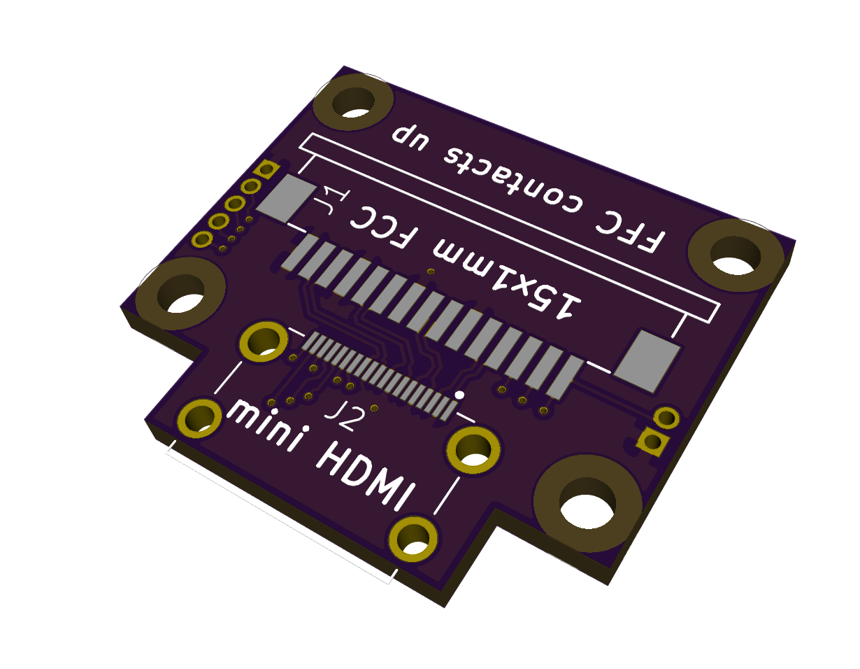
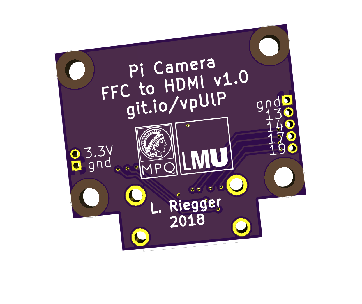
The purpose of this is to replace the fragile FFC connecting the Pi and the camera with a sturdier HDMI cable for "daily" camera use. The design is inspired by this extension board.
This repository contains the KiCAD schematic, the PCB layout file for the adapter board and instructions for operation and assembly.
The required parts for assembly are listed in the schematic, esentially
The FFC is inserted into the 15pin connector from one side and the 15 lanes are routed to a subset of the 19 HDMI lanes in a female mini HDMI receptacle. The four differential data lanes from the camera are mapped to the four HDMI data lanes to preserve the signal quality over the length of the HDMI cable.
There are 4 M2 mounting holes for stacking the board onto the Pi Camera.
The 4 remaining free lanes of the HDMI cable (13, 14, 17, 19) as well as the ground and 3.3V signals are broken out on the board for convenience.
A copy of our converter board can be ordered from OSH park:

| Qty | Value | Footprint | References |
|---|---|---|---|
| 1 | Conn_01x02 | lib-fp:PinHeader_1x02_P1.27mm_Vertical | J4 |
| 1 | Conn_01x05 | lib-fp:PinHeader_1x05_P1.27mm_Vertical | J3 |
| 1 | FPC68611514122 | lib-fp:68611514122 | J1 |
| 1 | HDMI-685119136923 | lib-fp:685119136923 | J2 |
| 1 | LOGO | lib-fp:LOGO | G*** |
The 5 most common of 9 parts.


FrameworkComputer/ExpansionCards
Reference designs and documentation to create Expansion Cards for the Framework Laptop

VoronDesign/Voron-Hardware
Cool Hardware designed by the Voron Design group

hackclub/OnBoard
💡 Join 1,000 teenagers and make your first PCB with a $100 grant!


adamws/kicad-kbplacer
KiCad plugin for automatic keyboard's key placement and routing
It measures 25 × 22 mm and has 2 copper layers, 1.6 mm thick.
9 parts. The full list of its parts is on this page, with links to each part's symbol and footprint where PCBKit's library has them.
From the himbeles/picamera-hdmi repository on GitHub, at the commit this page was made from: the board is picamera-hdmi.kicad_pcb. PCBKit opens the board in the browser, with nothing to install.
Its repository publishes it under the MIT licence: you may reuse it on that licence's terms (keep the author's notice, and for a copyleft licence share your changes alike).