Affordable Hardware-in-the-Loop Simulation (HILS) for ROS 2 robots, using inexpensive microcontrollers and off-the-shelf USB devices to test the full communication stack including physical interfaces.
FT234X cross connection board is an open-source printed circuit board by hijimasa, from the hijimasa/ros_hardware_in_the_loop_system repository on GitHub, published under the MIT licence. It is a 2-layer board of 34.9 × 20 mm with 2 parts on 5 nets, routed with 10 tracks and 0 vias.
Affordable Hardware-in-the-Loop Simulation (HILS) for ROS 2 robots, using inexpensive microcontrollers and off-the-shelf USB devices to test the full communication stack including physical interfaces.
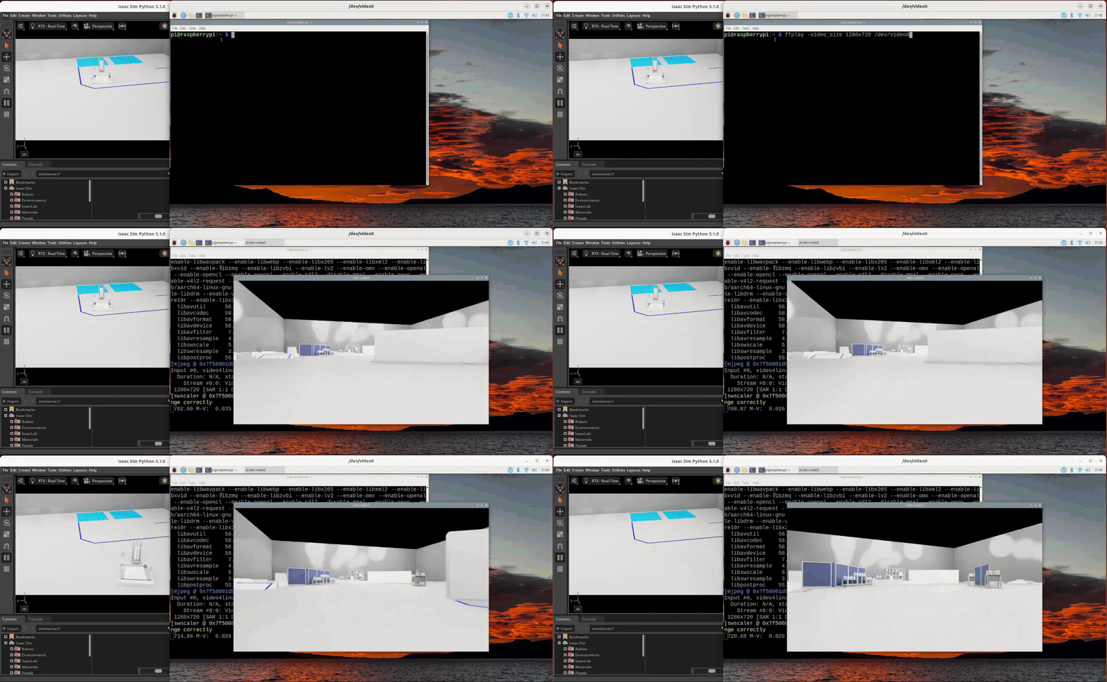
UVC camera verification (streaming simulation video from Isaac Sim)
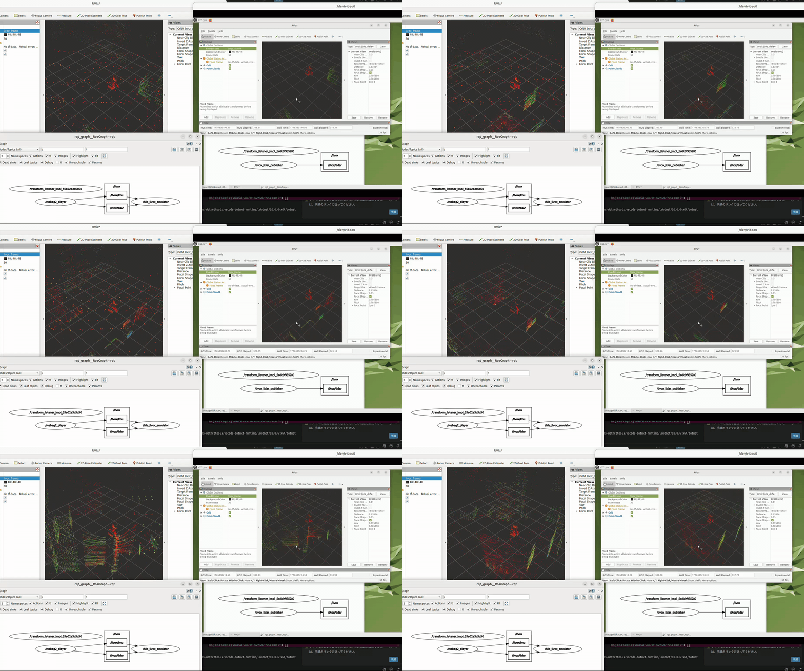
Livox MID360 verification (transmitting ros2 bag data via the native Livox SDK2 protocol)
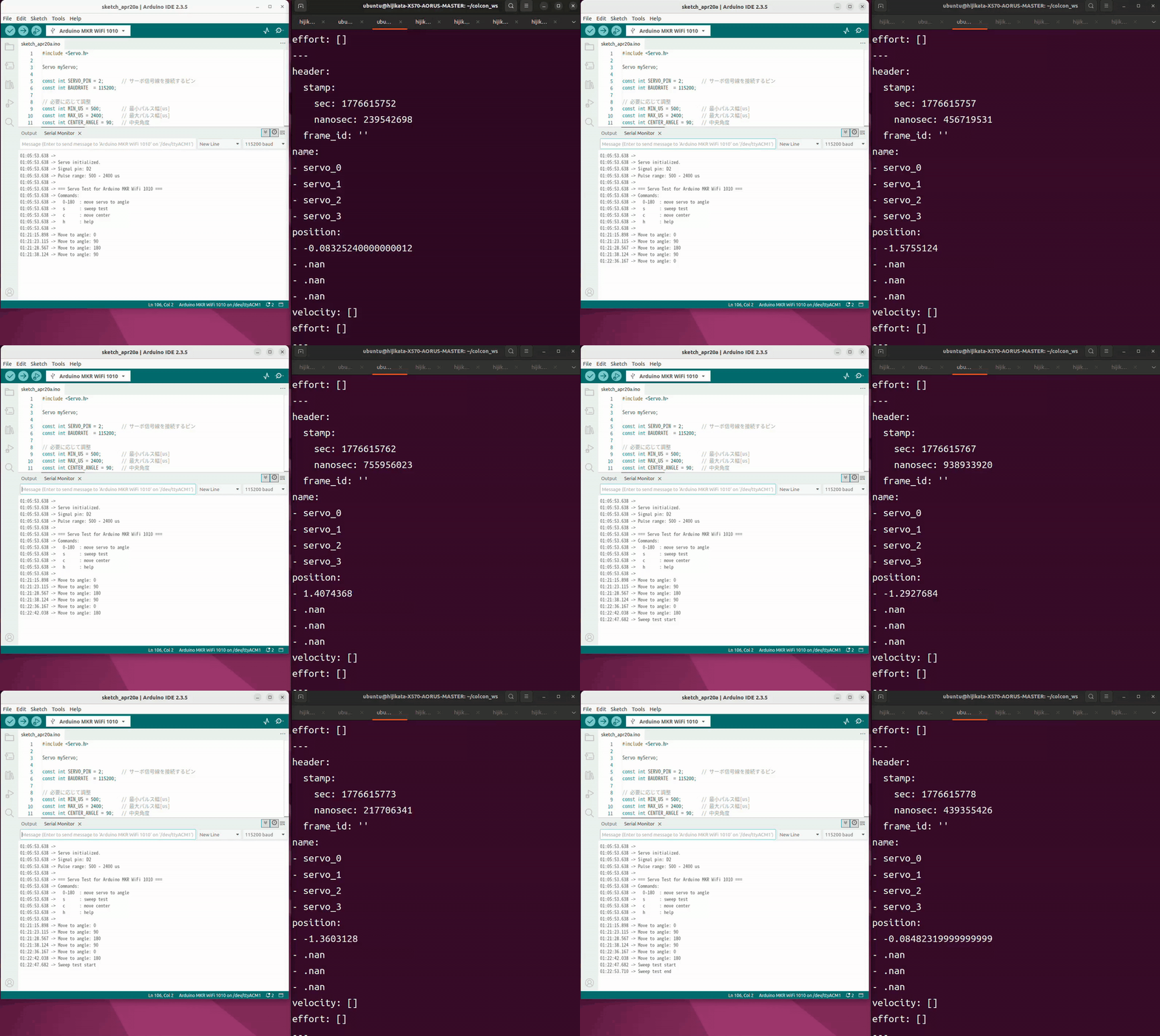
RC servo PWM capture verification (measuring the PWM signal from an Arduino controller and publishing it as JointState)
Overview
Software simulators (Gazebo / Unity / Isaac Sim) publish directly to ROS topics, which means the actual sensor drivers and physical communication paths (UDP, UART, USB, I2C, etc.) are never tested. This project bridges that gap by converting simulator outputs into device-native protocols, so the real-hardware driver sees what it would see from a real sensor -- all for under $30 in parts.
<protocol_or_vendor_series> — chosen by the following rule:
Industry-standard protocol (UVC, NMEA0183, PWM, quadrature, …): use the protocol name itself, signaling that any vendor's device with that protocol works (e.g. hils_bridge_camera_uvc, hils_bridge_gps_nmea0183)
Vendor-specific protocol: use <vendor>_<series> so that the package's actual scope is unambiguous (e.g. hils_bridge_lidar_livox_mid360, hils_bridge_imu_witmotion_wt901, hils_bridge_imu_invensense_mpu6050). Even within one vendor, generations or series often break compatibility, so always include the series
When adding a new emulator, decide the sensor type, then pick the standard protocol name if the implementation truly works across vendors, otherwise the <vendor>_<series> form. Keep the ROS package name and the corresponding firmware directory in lockstep.
Implementation Status
Track A: PC-based developers (no microcontroller needed)
Device
Method
ROS Package
Firmware
Status
Livox Mid-360
USB-LAN + SW
hils_bridge_lidar_livox_mid360
N/A
Implemented, verified (incl. fault-injection regression vs livox_ros_driver2)
cd ~/colcon_ws/src
git clone --recursive https://github.com/<your-org>/ros_hardware_in_the_loop_system.git
# Or clone only the ROS packages:# git clone https://github.com/<your-org>/ros2_hils_bridge.git
cd ~/colcon_ws
colcon build
source install/setup.bash
Building firmware (RP2040 only)
bash
cd firmware/rp2040_camera_uvc
mkdir build && cd build
cmake .. -DPICO_SDK_PATH=~/pico-sdk
make -j$(nproc)# Copy build/rp2040_camera_uvc.uf2 to Pico in BOOTSEL mode
Checking the normal path
Every emulator is checked the same way: feed it sensor data on the
simulation side, run the real vendor driver on the robot side, and
confirm the driver's own topic. Wiring, IP addresses and container
layout are in the Verification Guide;
what follows is the check itself.
For the YVT-35LX there is a demo script that brings the whole normal
path up and leaves it running with RViz — unlike the E2E, which exits
as soon as the oracle has judged:
bash
bash ros2_hils_bridge/tools/run_yvt35lx_demo.sh # Ctrl-C, or close RViz, to stop
It injects no faults; the banner it prints has a copy-paste command if
you want to trigger one by hand while it runs. Because its scene is
noise-free, it switches the emulator's sensor noise on (20 mm range
sigma, 1 % dropout) — that noise is off by default so it cannot double
up with a simulation that models its own. For the other sensors,
or to set RViz up yourself:
bash
rviz2
# Global Options -> Fixed Frame: the cloud's frame (see below)# Add -> By topic -> <topic> -> PointCloud2# PointCloud2 -> Color Transformer: Intensity
The fixed frame must match the cloud, otherwise RViz shows nothing:
Reading a YVT-35LX cloud. A flat wall appears as a row of U-shaped
traces, not a filled surface and not vertical stripes. That is the scan
pattern: the mirror oscillates at 1200 Hz while the rangefinder samples
at 88800 points/s, so one oscillation is 74 points — one VSSP line. A
20 Hz revolution holds 60 oscillations, of which the 210°/360° inside
the field of view are measured, giving 35 lines and 35 x 74 = 2590
points per frame. Within a line the elevation traces one full period of
a sine (middle → +35° → middle → −5° → middle) while the azimuth
advances 6°, so the traces join into a continuous wave across the field
of view. The sensor looks up rather than down: ±105° horizontal,
−5°…+35° vertical. Feeding a 10 m wall, a 2.5 m ceiling and a 0.5 m
pillar reconstructs across −105.0…+105.0° azimuth and −4.8…35.0°
elevation.
Automated pass/fail
For the LiDARs the normal path is also covered by one-command
regressions that bring the whole chain up, inject faults and let the
test oracle judge — see the Verification
Guide and ros2_hils_bridge/tools/:
The YVT-35LX one needs no hardware and no second container, so it is
the quickest way to see the whole chain run:
bash
bash docker/build_docker_image.sh    # once; the image carries urg3d_node2
bash docker/launch_docker.sh
# inside the container:
cd ~/colcon_ws && colcon build --packages-up-to hils_bringup \
  hils_bridge_lidar_hokuyo_yvt35lx urg3d_node2 && source install/setup.bash
bash src/ros2_hils_bridge/tools/run_yvt35lx_e2e.sh   # exit 0 = all expectations pass
For Ouster, the emulator exposes HTTP REST API on port 80, so Docker requires sysctls: net.ipv4.ip_unprivileged_port_start=80. See docs/hils_verification_guide.md for details. ↩
The YVT-35LX emulator speaks VSSP 2.1 over TCP (control and measurement multiplexed on one socket), so no extra NIC is needed for the loopback E2E: bash ros2_hils_bridge/tools/run_yvt35lx_e2e.sh drives the real urg3d_node2. Like every other driver under test it is not vendored in this repository; the docker image clones it into the workspace (as it already does for livox_ros_driver2 and witmotion_ros), or you can git clone --recursive https://github.com/Hokuyo-aut/urg3d_node2 into your own colcon workspace (needs ros-<distro>-laser-proc and ros-<distro>-diagnostic-updater). That regression also surfaced a driver defect — byte corruption on the VSSP stream segfaults urg3d_node2 — recorded in docs/fault_injection_implementation_policy.md section 22.5. ↩
The IMU emulator emits the four standard WT901 packets (0x51 Accel / 0x52 Gyro / 0x53 Euler / 0x59 Quaternion) so it works with witmotion_ros (ElettraSciComp) at default use_native_orientation: true. Driver build needs libqt5serialport5-dev (already in the Dockerfile). See docs/hils_verification_guide.md for setup details. ↩
Parts
2
Qty
Value
Footprint
References
2
AE-FT234X
hils_modules:AE-FT234X
U1, U2
More from hijimasa/ros_hardware_in_the_loop_system
Affordable Hardware-in-the-Loop Simulation (HILS) for ROS 2 robots, using inexpensive microcontrollers and off-the-shelf USB devices to test the full communication stack including physical interfaces.
It measures 34.9 × 20 mm and has 2 copper layers, 1.6 mm thick.
What parts does the FT234X cross connection board use?
2 parts. The full list of its parts is on this page, with links to each part's symbol and footprint where PCBKit's library has them.
Where can I download the FT234X cross connection board KiCad files?
From the hijimasa/ros_hardware_in_the_loop_system repository on GitHub, at the commit this page was made from: the board is hardware/schematics/FT234X_cross_connection_board/FT234X_cross_connection_board.kicad_pcb and its schematic hardware/schematics/FT234X_cross_connection_board/FT234X_cross_connection_board.kicad_sch. PCBKit opens the board in the browser, with nothing to install.
Can I use the FT234X cross connection board design in my own project?
Its repository publishes it under the MIT licence: you may reuse it on that licence's terms (keep the author's notice, and for a copyleft licence share your changes alike).