2 layers50 × 23.2 mm
Analog
hoglet67/RGBtoHDMI
Bare-metal Raspberry Pi project that provides pixel-perfect sampling of Retro Computer RGB/YUV video and conversion to HDMI
32 parts1kGPL-3.0

 henryrov/CHELYDRA
Board-level electromechanical ADC
Chelydra pcb is an open-source printed circuit board by henryrov, from the henryrov/CHELYDRA repository on GitHub, published under the CERN-OHL-W-2.0 licence. It is a 2-layer board of 71.1 × 35.6 mm with 32 parts on 35 nets, routed with 137 tracks and 0 vias.
Its parts include 9 resistors, 7 transistors, 7 switches, 6 capacitors and 2 ICs.
CHELYDRA is a board-level electromechanical charge redistribution analog-to-digital converter, plus an accompanying controller implementation written in SystemVerilog.
It has an integrated reference voltage of 1.024 V, 4 bits of resolution, and a sampling rate of approximately 8 Hz. Communication with the provided controller is done over UART at a fixed baud rate of 9600.
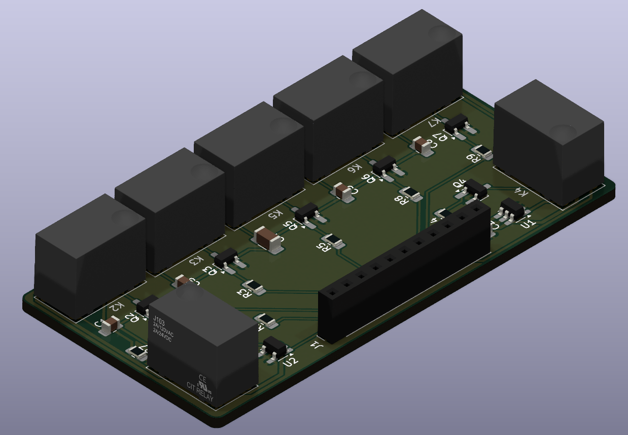
The PCB is simple and any commercial manufacturer should be able to produce it. It is designed such that it isn't too difficult to solder by hand. Components can be found in the included BOM. For the NPN transistors, I personally used the MMBT3904, but other transistors with the same pinout should also work. It is designed to operate at 3.3 V.
The provided controller is packaged in a Vivado project targetting an Arty S7-50. Hardware utilization is quite low, so it shouldn't be too difficult to port it to other boards or FPGAs.
Vivado likes to store absolute paths. In this repo the original paths have been modified so that they can be adapted after cloning. To do this, run the provided script ./specify_paths.sh, which will use the path where you have cloned the repo. To revert it to the original state, run ./generalize_paths.sh.
To start a single conversion, use a microcontroller or UART adapter to send 0x01 to the controller. To start free-running conversions, send 0x02 instead. At the end of each conversion, the controller will return the result also over UART. To stop free-running, send 0x00 and the controller will stop once the ongoing conversion is done.
| Qty | Value | Footprint | References |
|---|---|---|---|
| 8 | 1k | Resistor_SMD:R_0805_2012Metric_Pad1.20x1.40mm_HandSolder | R1, R2, R3, R4, R5, R7, R8, R9 |
| 7 | Q_NPN_BEC | Package_TO_SOT_SMD:SOT-23_Handsoldering | Q1, Q2, Q3, Q4, Q5, Q6, Q7 |
| 7 | Relay_SPDT | chelydra_lib:J103 | K1, K2, K3, K4, K5, K6, K7 |
| 2 | 24n | Capacitor_SMD:C_0805_2012Metric_Pad1.18x1.45mm_HandSolder | C5, C6 |
| 1 | 100n | Capacitor_SMD:C_0805_2012Metric_Pad1.18x1.45mm_HandSolder | C3 |
| 1 | 2.2u | Capacitor_SMD:C_0805_2012Metric_Pad1.18x1.45mm_HandSolder | C2 |
| 1 | 200n | Capacitor_SMD:C_0805_2012Metric_Pad1.18x1.45mm_HandSolder | C1 |
| 1 | 5.1k | Resistor_SMD:R_0805_2012Metric_Pad1.20x1.40mm_HandSolder | R6 |
| 1 | 50n | Capacitor_SMD:C_1206_3216Metric_Pad1.33x1.80mm_HandSolder | C4 |
| 1 | Conn_01x11_Socket | Connector_PinSocket_2.54mm:PinSocket_1x11_P2.54mm_Vertical | J1 |
| 1 | MCP1501-10xCH | Package_TO_SOT_SMD:SOT-23-6_Handsoldering | U1 |
| 1 | NCS2200SN1T1G | Package_TO_SOT_SMD:SOT-23-5_HandSoldering | U2 |
hoglet67/RGBtoHDMI
Bare-metal Raspberry Pi project that provides pixel-perfect sampling of Retro Computer RGB/YUV video and conversion to HDMI

hackclub/OnBoard
💡 Join 1,000 teenagers and make your first PCB with a $100 grant!


octosavvi/ESPKey
Wiegand data logger, replay device and micro door-controller

zmaker/arduino_cookbook
gli sketch del nuovo progetto Arduino Cookbook e dei video di YouTube

murexrobotics/electrical
Highly integrated electronics design and printed circuit boards (PCBs) for the MATE ROV Competition. Attempt the impossible.

swharden/AVR-projects
A collection of standalone AVR projects written in C

hardenedlinux/cheap-pcb
Cheap PCB: Better understanding the current status of hardware supply chain
It measures 71.1 × 35.6 mm and has 2 copper layers, 1.6 mm thick.
32 parts. The full list of its parts is on this page, with links to each part's symbol and footprint where PCBKit's library has them.
From the henryrov/CHELYDRA repository on GitHub, at the commit this page was made from: the board is chelydra_pcb/chelydra_pcb.kicad_pcb and its schematic chelydra_pcb/chelydra_pcb.kicad_sch. PCBKit opens the board in the browser, with nothing to install.
Its repository publishes it under the CERN-OHL-W-2.0 licence: you may reuse it on that licence's terms (keep the author's notice, and for a copyleft licence share your changes alike).