

2 layers55 × 55 mm
ILX544A V1 B2
altLab/AltoEspectro
Projecto de Uma Camara de CCD arrefecida para Espectroscopia, imagem de scanning, ou para fotografia panorâmica se utilizada com cabeça panorâmica.
29 parts1MIT

 heneault/TapeMate649
Connect your Commodore Datasette to a computer via USB
TapeMate64 is an open-source printed circuit board by heneault, from the heneault/TapeMate64 repository on GitHub. It is a 2-layer board of 47 × 70.1 mm with 10 parts on 31 nets, routed with 58 tracks and 6 vias.
It is built around the MT3608 and TIP125. Its parts include 4 ICs, 2 resistors, 1 capacitor and 1 transistor. It belongs with the retro computing and games boards and the AVR (ATmega, ATtiny) boards of this library.
TapeMate64 is a compact and affordable USB adapter that lets you connect a Commodore Datasette to your PC via USB for both reading and writing cassette data. It enables you to digitize original tapes for archiving or for use in an emulator—without needing a working Commodore 64.
It also allows you to write TAP images back to real cassette tapes, so you can enjoy software on original hardware for the full retro experience.
Watch the full presentation and live demo of TapeMate64 at the TPUG (Toronto PET Users Group) meeting (December 2025):
👉 TapeMate64 Presentation at TPUG - Watch on YouTube
TapeMate64 kits are available in my Tindie store.
Based on the TapeBuddy64 project, TapeMate64 adds a builder-friendly design. You can operate it via a command-line interface or a Python-based graphical front-end.
The main differences of TapeMate64 over the original TapeBuddy64 project are:
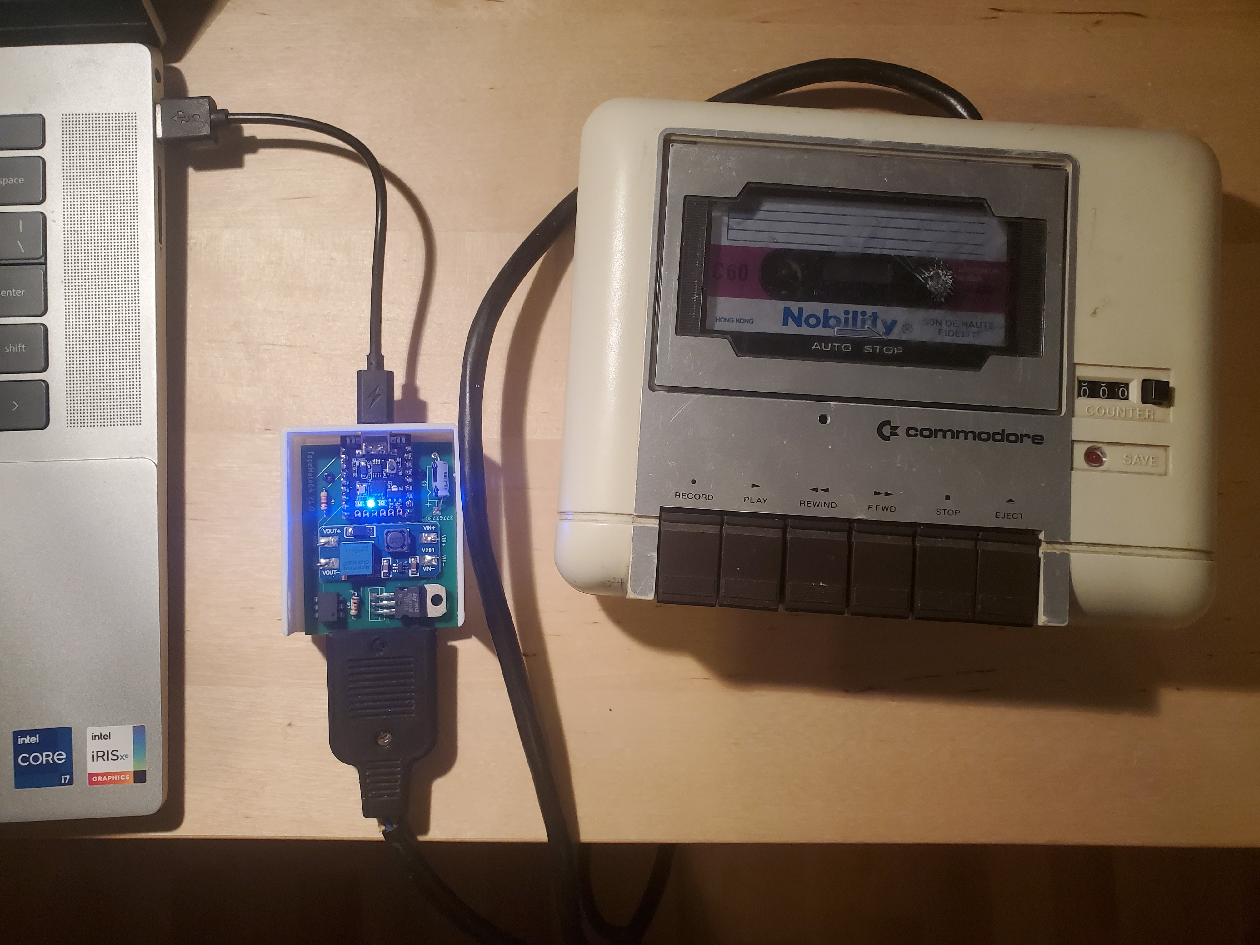
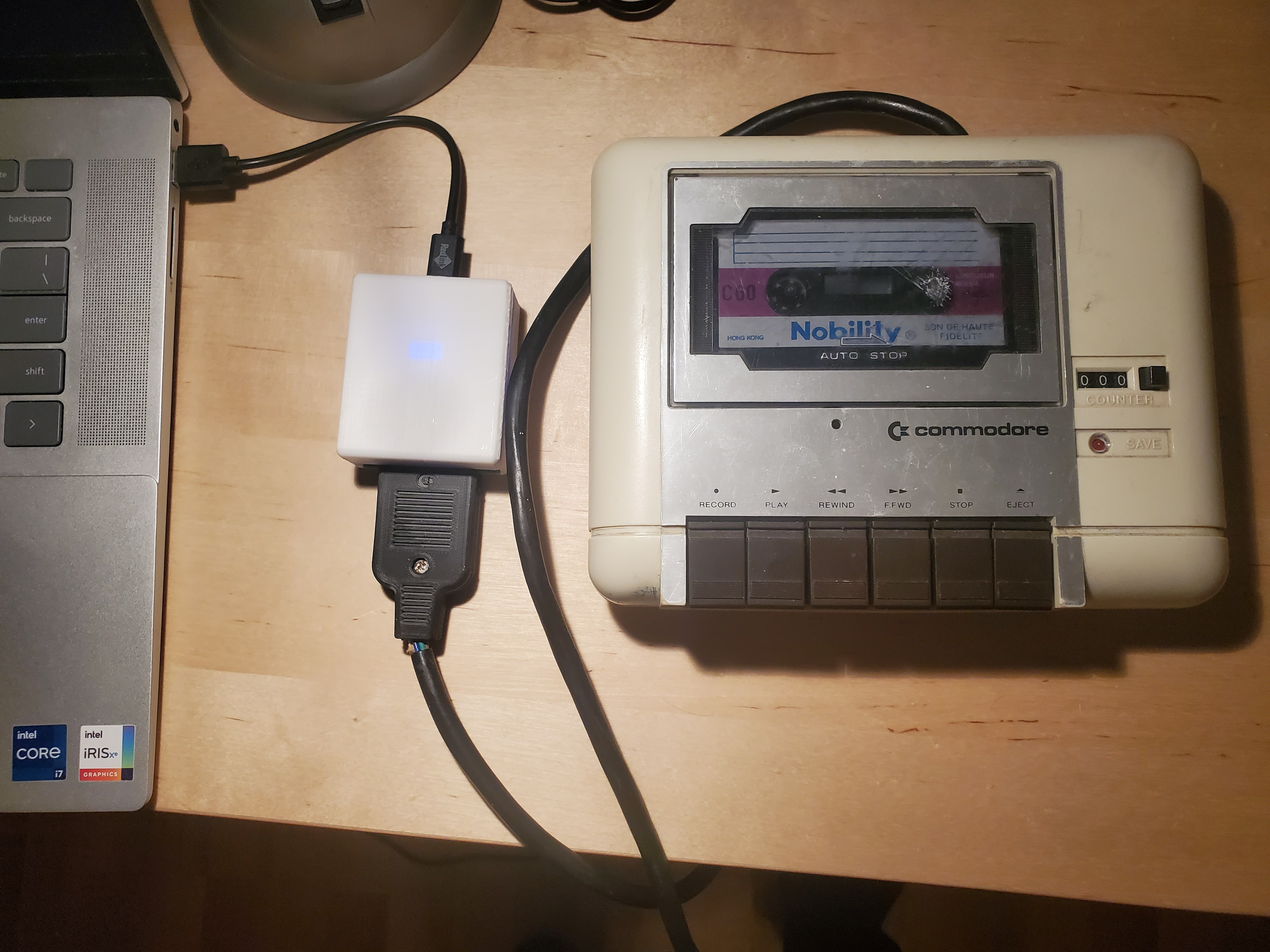
To properly build and calibrate your TapeMate64, please follow the steps in the build instructions. Carefully adjusting the MT3608 is very important to avoid damaging your Datasette.
The latest application release can be downloaded here. Download the zip file corresponding to your operating system (Windows or Linux). Extract the entire zip file to access the different applications.
Windows users may need to install a driver for the CH340N USB-to-serial adapter. If the application does not detect the board, install the driver, reboot your PC, and try again.
tape-gui.exe.flash-firmware.exe.The following command-line tools are available:
tape-read.exe outputfile.tap.tape-write.exe inputfile.tap.tape-gui.exe.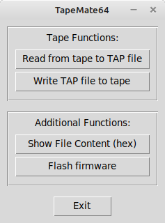
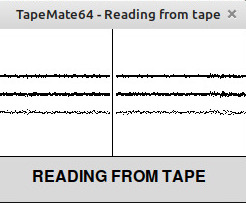
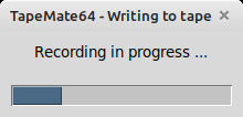
| LED | Description |
|---|---|
| Blue | Steady: Device is powered via USB. |
| Green | Steady: Device is reading from the tape. Flashing: Device waits for the PLAY or STOP button to be pressed. |
| Red | Steady: Device is writing to the tape. Flashing: Device waits for the RECORD or STOP button to be pressed. |
If you experience buffer underrun or overrun errors, especially on Windows, please check the following:
The schematic is shown below:
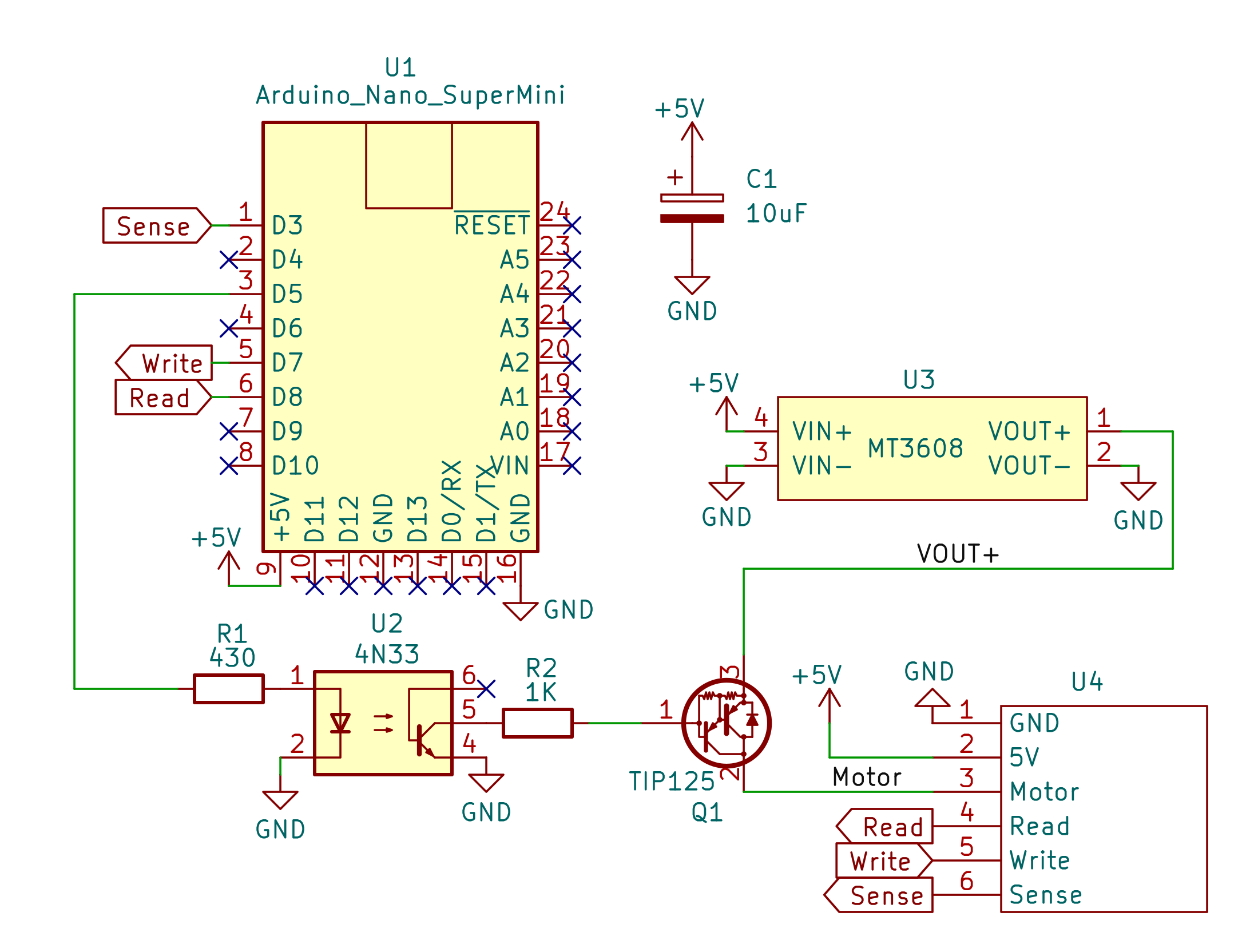
The heart of the system is an Arduino Nano Super Mini. This board is similar to a classic Arduino Nano but has a smaller footprint and includes onboard LEDs. It's a very popular board and includes the necessary voltage regulator and USB-to-serial chip, making it an excellent choice for this project. The USB port is used both for flashing the firmware and for operating the device. The microcontroller on the board is a widely supported ATmega328.
The MT3608 boost converter is used to provide the approximately 6 Volts required for the Datasette's motor. The ATmega can switch the motor on and off via an optocoupler and a transistor when a key press is detected on the Datasette.
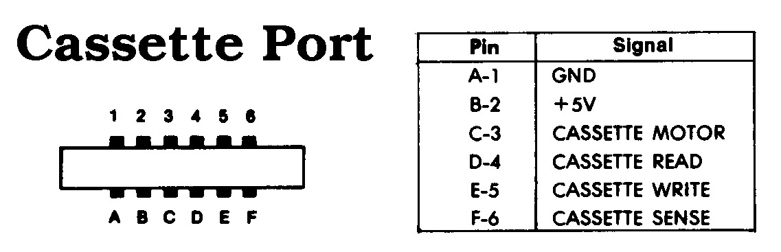
The cassette port is a 6-pin edge connector integrated into the printed circuit board (PCB) with a 3.96mm spacing. The Datasette's connector plugs directly onto this port. A notch between pins B/2 and C/3 prevents accidental polarity reversal.
| Pin | Signal | Description |
|---|---|---|
| A / 1 | GND | Ground |
| B / 2 | +5V | 5 Volt DC |
| C / 3 | MOTOR | Motor Control, approx. 6 Volt power supply for the motor. |
| D / 4 | READ | Data Input, read data from the Datasette. |
| E / 5 | WRITE | Data Output, write data to the Datasette. |
| F / 6 | SENSE | Detection, senses if one of the PLAY, RECORD, F.FWD, or REW keys is pressed. |
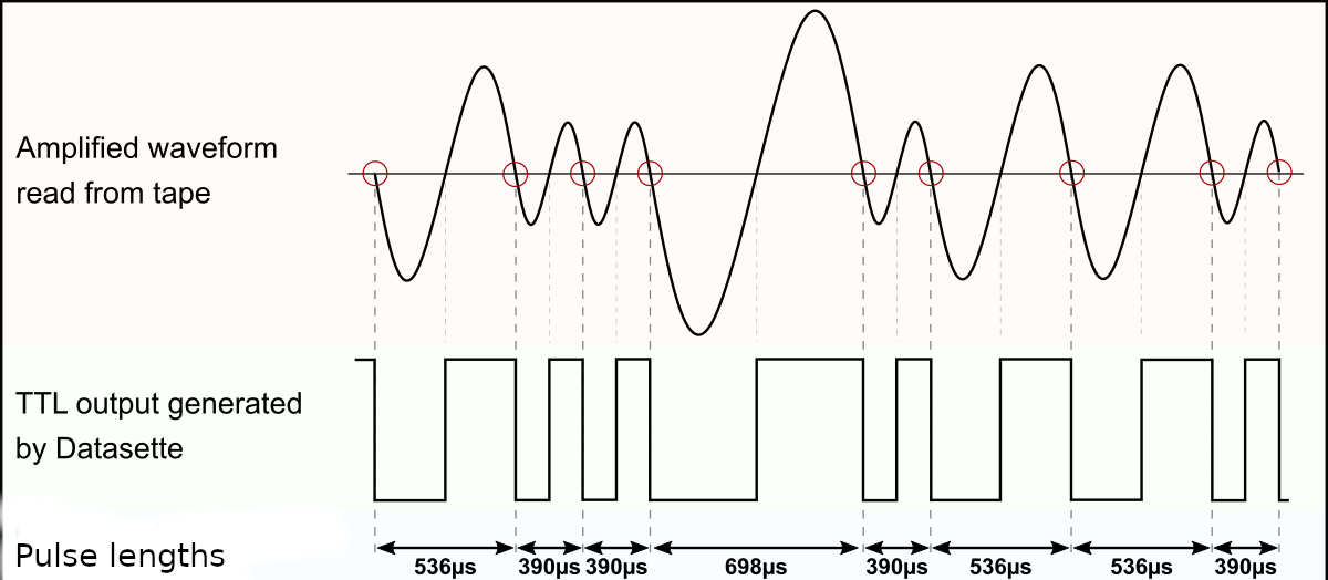
Data is stored on the tape as a frequency-modulated waveform. This signal is read from the Datasette, amplified, converted into a TTL-level square wave with the same pulse lengths, and then output to the cassette port's READ pin. TapeMate64 reads this square wave and measures the pulse durations between the signal's falling edges. These pulse lengths are then sent to the PC via USB and written into the TAP file in the correct format after being adjusted using the clock frequency.
Writing to tape works in the opposite way. TapeMate64 generates a square wave with the corresponding pulse lengths based on the TAP data values (the signal is inverted when writing) and sends it through the WRITE pin to the Datasette, which then generates the corresponding waveform and records it onto the cassette.
The actual data is encoded using a sequence of pulses of different lengths. The standard Commodore system uses patterns of three different pulse lengths: short ($390\mu\text{s}$), medium ($536\mu\text{s}$), and long ($698\mu\text{s}$).
However, fast loaders are often used, and each one uses different pulse lengths and patterns, which complicates the overall decoding. Fortunately, TapeMate64 does not need to decode the data. This is because only the raw data—the individual pulse lengths—is saved in the TAP file. The actual interpretation of these pulses is handled later by the C64 or a corresponding emulator.
The accuracy of the pulse lengths depends on various factors. For instance, not all motors in Datasettes run at exactly the same speed. Additionally, the C64 measures the pulse length via the CIA timer as the number of elapsed system clock cycles, but PAL versions of the C64 have a different clock frequency ($985248 \text{ Hz}$) than NTSC versions ($1022730 \text{ Hz}$). Furthermore, badly aligned Datasette heads and old tapes with weakened signals also contribute to potential timing variations.
For these reasons, the difference between the individual pulse lengths used for data encoding is large enough to be reliably distinguished even under the circumstances mentioned. In fact, what matters is not the measured pulse length itself, but whether it is above or below a defined threshold value. Moreover, turbo loaders often employ a mechanism to synchronize with the data stream from the Datasette.
The TAP file format attempts to duplicate the data stored on a C64 cassette tape, bit for bit. It was designed by Per Håkan Sundell (author of the CCS64 C64 emulator) in 1997. Since it is simply a representation of the raw serial data from a tape, it should be able to handle any custom tape loaders that exist. The layout is fairly simple, with a small 20-byte header followed by the file data:
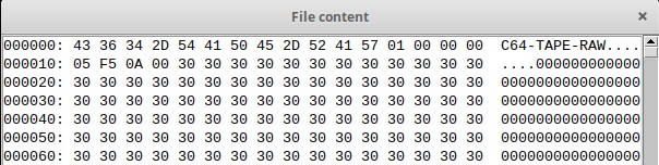
| Bytes (hex) | Description |
|---|---|
| 0000-000B | File signature "C64-TAPE-RAW" |
| 000C | TAP version (0 - original, 1 - updated, 2 - halfwave extension) |
| 000D | Computer platform (0 - C64, 1 - VIC-20, 2 - C16, Plus/4, 3 - PET) |
| 000E | Video standard (0 - PAL, 1 - NTSC, 2 - OLD NTSC, 3 - PALN) |
| 000F | Future expansion |
| 0010-0013 | File data size (little endian; not including the header) |
| 0014-xxxx | File data |
In TAP version 0, each data byte in the file data area represents the length of a single pulse, determined by the following formula: $$\text{data byte} = \frac{\text{pulse length (in seconds)} \times \text{C64 clock frequency (in Hertz)}}{8}$$
Therefore, the data value for a pulse length of $390\mu\text{s}$ would be: $$0.000390\text{s} \times 985248\text{Hz} / 8 \approx 48 \quad (0\text{x}30 \text{ in hex})$$
A data value of $0\text{x}00$ represents an "overflow" condition—any pulse length greater than $255 \times 8$ clock cycles (or $2078\mu\text{s}$). Such a pulse length does not encode any data and typically only occurs in the pauses between programs on the same tape. However, the lengths of these pauses can be relevant for some fast loaders.
In TAP version 1, the data value of $0\text{x}00$ was re-coded to represent values greater than $255 \times 8$ clock cycles, or to provide a greater resolution (one clock cycle instead of eight). When a $0\text{x}00$ is encountered, it is followed by three bytes that represent the actual pulse length in C64 clock cycles. These three bytes are stored in little-endian format (least significant byte first). For example, a data value for a pulse length of $2875\mu\text{s}$ would be: $$0.002875\text{s} \times 985248\text{Hz} \approx 2832 \quad (\text{data bytes: } 0\text{x}00, 0\text{x}10, 0\text{x}0\text{B}, 0\text{x}00)$$
TAP Version 2 is an extension made by Markus Brenner for C16 tapes. It is based on Version 1, but each value represents a halfwave, starting with a '0' to '1' transition. The time encoding remains the same.
TapeMate64 can read TAP versions 0 and 1 and write them to cassette. It uses TAP version 1 to generate a TAP file when reading from the Datasette. The pauses between individual files on the tape are also precisely recorded, ensuring the device should be able to handle all types of fast loaders.
The Python scripts on the PC control the device via four simple serial commands:
| Command | Function | Response |
|---|---|---|
| "i" | Transmit identification string | "TapeMate64\n" |
| "v" | Transmit firmware version number | e.g. "v1.0\n" |
| "r" | Read file from tape | Send raw data stream |
| "w" | Write file on tape | Receive raw data stream |
The ATmega measures the pulse lengths using its Timer 1.
The Python script writes the TAP file header, converts the received data words into the corresponding TAP values, and writes them to the output file.
Long Pulses and Duty Cycle: Very long pulses can sometimes cause the Datasette to misinterpret the signal. If we use a fixed 50% duty cycle, the signal will remain too long during the first half of a long pulse. This cause the Datasette's internal electronics to prematurely detect the pulse's edge and switch to the second half of the cycle, leading to recording errors (false pulses).
To avoid this, the implementation briefly adjusts the duty cycle at the beginning of a long pulse. It first quickly performs the required edge transition by outputting a very short pulse of the opposite polarity. After this quick transition, it holds the output steady for the remaining duration of the long pulse. This approach ensures a clean, sharp edge at the start of the pulse, preventing glitches or false triggers on the tape and guaranteeing reliable timing.
Timer Interrupt Conflicts: Another potential issue during writing occurs when a pulse period is slightly longer than the timer's maximum representable value. The timer would first wait for its maximum period, then wait for a very small remainder. If this remainder is too close to zero, the interrupt handler may not have enough time to react. The compare register could immediately re-trigger the interrupt while the current interrupt is still being processed. This results in the timer running past the intended point, overflowing to zero, continuing to count, and eventually triggering the interrupt much later than expected—producing an unintended, very long pulse. To prevent this, the code splits any pulse period that slightly exceeds the timer’s limit into two roughly equal halves. This guarantees that each timer period is long enough for the interrupt handler to run reliably and avoids spurious long pulses.
Follow these steps to compile the firmware yourself:
TapeMate64/software/avr).platformio.ini file..pio/build/nanoatmega328/.COM3 on Windows or /dev/ttyUSB0 on Linux/macOS).If you want to modify the application running on the computer, you need to have Python installed on your PC. Most Linux distributions already include this. Windows users can follow these instructions.
You should also create a virtual environment to install the required dependencies, following these steps:
cd TapeMate64/software/pcvenv):
python3 -m venv venvsource venv/bin/activatepip install -r requirements.txtThe TAP files generated by TapeMate64 can be used directly in your favorite emulator, but you might want to check, optimize, or convert them beforehand. This works perfectly with the command-line tool TAPClean.
tapclean -t outputfile.tap
Remember that a TAP file is almost never 100% clean, as pauses in particular are not always correctly recognized.tapclean -o outputfile.tap
This compensates for slight deviations in the pulse lengths and adapts everything to the exact timing specifications. TAPClean knows the required pulse lengths not only for the standard Commodore coding but also for all common fast loaders.tapclean -wav outputfile.tapThere is also a graphical front end available for TAPClean.
If you have trouble loading programs from tape, the azimuth of the tape head may be out of position. Before adjusting the azimuth, however, you should rule out all other causes of error:
If it still doesn't work, it's time for the screwdriver.
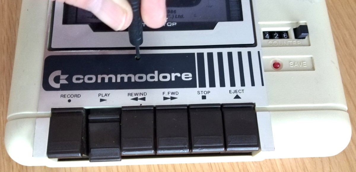
To adjust the azimuth, there is a tiny screw hole above the rewind button through which a small jeweler's screwdriver can fit. When the tape drive is playing, the hole will align with the head adjustment screw. Do not apply too much pressure and avoid over-tightening or over-loosening the screw!
Follow these steps:
tape-gui.exe.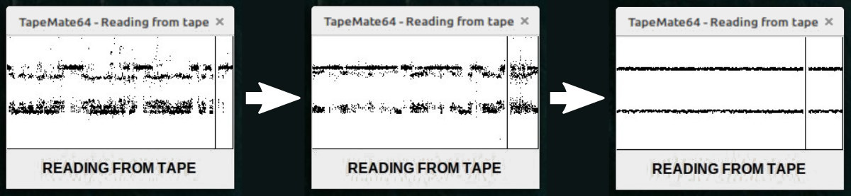

This work is licensed under the Creative Commons Attribution-ShareAlike 3.0 Unported License. (http://creativecommons.org/licenses/by-sa/3.0/)
| Qty | Value | Footprint | References |
|---|---|---|---|
| 1 | 10uF | Capacitor_THT:CP_Axial_L11.0mm_D5.0mm_P18.00mm_Horizontal | C1 |
| 1 | 1K | Resistor_THT:R_Axial_DIN0204_L3.6mm_D1.6mm_P7.62mm_Horizontal | R2 |
| 1 | 430 | Resistor_THT:R_Axial_DIN0204_L3.6mm_D1.6mm_P7.62mm_Horizontal | R1 |
| 1 | 4N33 | Package_DIP:DIP-6_W7.62mm | U2 |
| 1 | Arduino_Nano_SuperMini | footprint:Nano_V3_SuperMini | U1 |
| 1 | MT3608 | footprint:MT3608 | U3 |
| 1 | TIP125 | Package_TO_SOT_THT:TO-220-3_Vertical | Q1 |
| 1 | ~ | footprint:EDGE_CON_12P_TAPE | U4 |
The 8 most common of 10 parts.
It measures 47 × 70.1 mm and has 2 copper layers, 1.6 mm thick.
10 parts, built around the MT3608 and TIP125. The full list of its parts is on this page, with links to each part's symbol and footprint where PCBKit's library has them.
From the heneault/TapeMate64 repository on GitHub, at the commit this page was made from: the board is hardware/TapeMate64.kicad_pcb and its schematic hardware/TapeMate64.kicad_sch. PCBKit opens the board in the browser, with nothing to install.
Its repository states no licence, so its author keeps all rights: ask heneault before reusing the design.
altLab/AltoEspectro
Projecto de Uma Camara de CCD arrefecida para Espectroscopia, imagem de scanning, ou para fotografia panorâmica se utilizada com cabeça panorâmica.


LouDnl/USBSID-Pico
USBSID-Pico is a RPi Pico (RP2040/W RP2350/W) based board for interfacing one or two MOS SID chips and/or hardware SID emulators over (WEB)USB with your computer, phone, ASID supporting player or USB midi controller


cester-ino/OTTO-hardware
those specs refer to the tactile buttons version, but a led backlight button version is in the works too.

MR-DOS/TDR_diploma_thesis
Time domain reflectometer. Includes Hardware, firmware and GUI in Octave. Also a diploma thesis.