
4 layers159.1 × 99.9 mm

 heinzmmo/light-barrier-array1
Photoelectric Sensor Array for STM32F767 Eval-Board
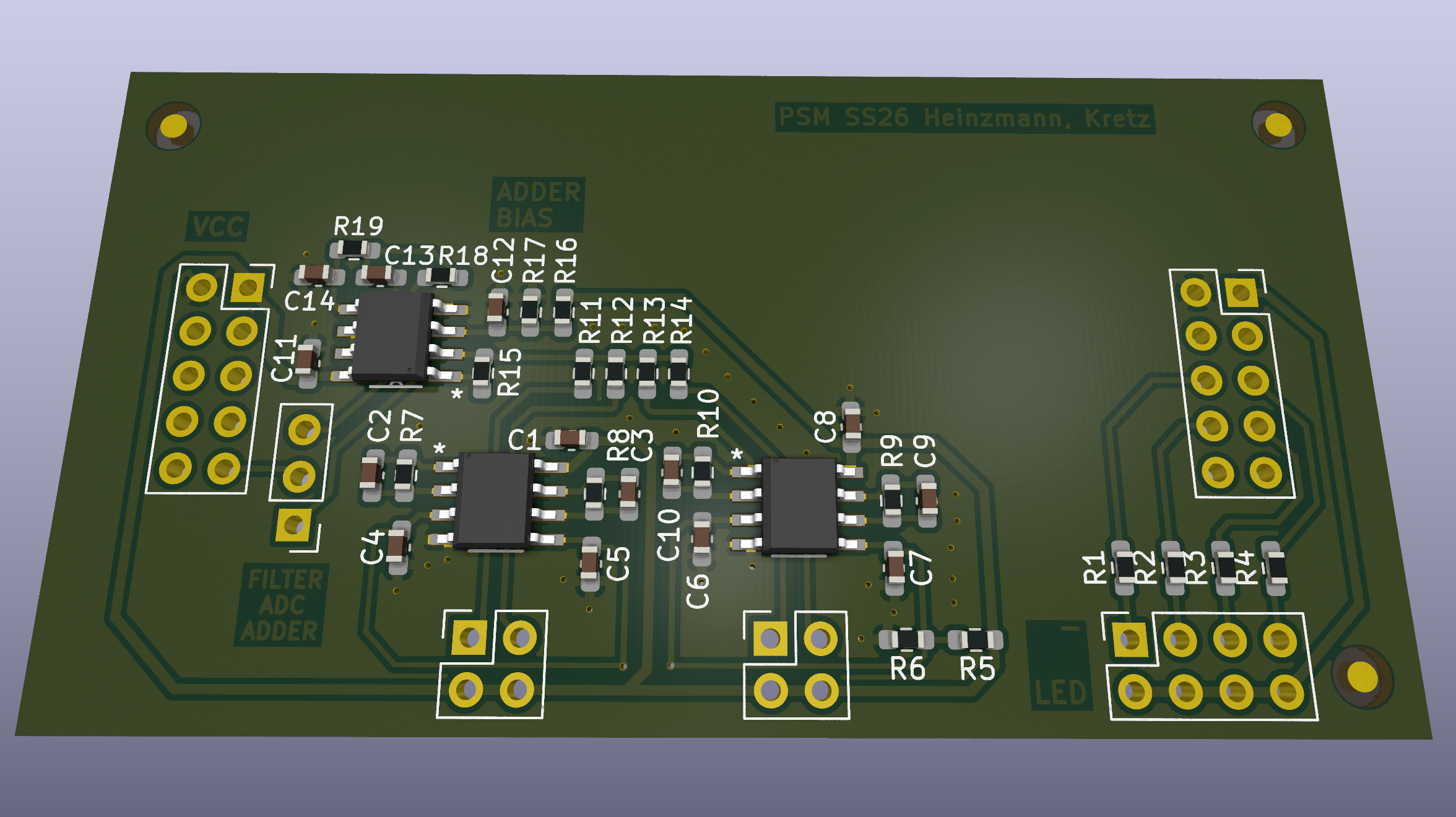
PSM HeinzmannKretz is an open-source printed circuit board by heinzmmo, from the heinzmmo/light-barrier-array repository on GitHub, published under the MIT licence. It is a 2-layer board of 70 × 37 mm with 48 parts on 37 nets, routed with 211 tracks and 35 vias.
It is built around the AD8646ARZ. Its parts include 19 resistors, 14 capacitors, 6 connectors and 3 ICs. It belongs with the sensors and measurement boards of this library.
As part of the Sensor Technology and Mechatronics Project Lab, an photoelectric sensor array (light barrier array) was designed to detect beam interruptions simultaneously using a single analog signal line.
The project focused on the development of the analog electronics, the circuit design and simulation, the design of the PCB, and the implementation of the firmware for digital signal processing and evaluation.
project/
├── docs                   # Technical documentations
│   ├── datasheets
│   └── manuals
├── firmware               # STM32CubeMX Project
├── pcb
│   ├── .kicad_xxx
│   └── postpr             # Manufactoring outputs (Gerber, Drill...)
├── README.md
├── report                 # Project report (LaTeX source) + Compiled PDF
├── sandbox                # Test env (ignored)
└── sim # LTspice & Python simulations Each light barrier consists of an LED–photodiode pair driven by pulse-width-modulated (PWM) signals at unique frequencies ($3\text{ kHz}$, $5\text{ kHz}$, $7\text{ kHz}$, and $9\text{ kHz}$). The optical signals are received by BPW34 photodiodes operated in reverse-bias (photoconductive) mode to maximize response speed and bandwidth. The photodiode currents are converted to voltages via individual Transimpedance Amplifiers (TIA), additively combined in an inverting summing amplifier stage, filtered using a 2nd-order Sallen-Key low-pass filter ($f_c \approx 15.6\text{ kHz}$), and digitized by an STM32 microcontroller ADC. Digital signal processing is performed via Fast Fourier Transform (FFT) to simultaneously evaluate all four channels.
As a practical application, a digital logic game was implemented in firmware where users enter a randomized 6-digit passcode (generated via True Random Number Generator - TRNG) by selectively breaking the light barriers (each representing a binary bit from 1 to 15).
arm_rfft_fast_f32), providing a frequency bin resolution of
$\Delta f = f_s / N \approx 39.06\text{ Hz}$. Energy across 5 adjacent bins
surrounding each target frequency ($3\text{ kHz}$, $5\text{ kHz}$, $7\text{ kHz}$,
$9\text{ kHz}$) is integrated to detect channel presence/absence robustly against
spectral leakage.Format auto-generated Makefile:
cd firmware/
dos2unix Makefile
Generate compile_commands.json for LSP (from Makefile)
cd firmware/
bear -- makeGNU Arm Embedded Toolchain
sudo apt install gcc-arm-none-eabisudo dnf install arm-none-eabi-gcc arm-none-eabi-newlib arm-none-eabi-binutils-cs | Qty | Value | Footprint | References |
|---|---|---|---|
| 8 | 100n | Capacitor_SMD:C_0603_1608Metric_Pad1.08x0.95mm_HandSolder | C1, C4, C5, C6, C7, C8, C11, C12 |
| 8 | 10k | Resistor_SMD:R_0603_1608Metric_Pad0.98x0.95mm_HandSolder | R5, R11, R12, R13, R14, R17, R18, R19 |
| 6 | Fiducial | Fiducial:Fiducial_1.5mm_Mask3mm | FID1, FID2, FID3, FID4, FID5, FID6 |
| 4 | 270k | Resistor_SMD:R_0603_1608Metric_Pad0.98x0.95mm_HandSolder | R7, R8, R9, R10 |
| 4 | 5p | Capacitor_SMD:C_0603_1608Metric_Pad1.08x0.95mm_HandSolder | C2, C3, C9, C10 |
| 4 | R | Resistor_SMD:R_0603_1608Metric_Pad0.98x0.95mm_HandSolder | R1, R2, R3, R4 |
| 3 | AD8646ARZ | psm_ss26:SOIC127P600X175-8N | U1, U2, U3 |
| 2 | 1n | Capacitor_SMD:C_0603_1608Metric_Pad1.08x0.95mm_HandSolder | C13, C14 |
| 2 | Conn_02x02_Odd_Even | Connector_PinSocket_2.54mm:PinSocket_2x02_P2.54mm_Vertical | J2, J4 |
| 2 | Conn_02x05_Odd_Even | Connector_PinSocket_2.54mm:PinSocket_2x05_P2.54mm_Vertical | J8, J9 |
| 1 | 2.5k | Resistor_SMD:R_0603_1608Metric_Pad0.98x0.95mm_HandSolder | R15 |
| 1 | 22k | Resistor_SMD:R_0603_1608Metric_Pad0.98x0.95mm_HandSolder | R16 |
| 1 | 47k | Resistor_SMD:R_0603_1608Metric_Pad0.98x0.95mm_HandSolder | R6 |
| 1 | Conn_01x03_Pin | Connector_PinHeader_2.54mm:PinHeader_1x03_P2.54mm_Vertical | J19 |
| 1 | Conn_02x04_Odd_Even | Connector_PinSocket_2.54mm:PinSocket_2x04_P2.54mm_Vertical | J1 |


hackclub/OnBoard
💡 Join 1,000 teenagers and make your first PCB with a $100 grant!

adamws/kicad-kbplacer
KiCad plugin for automatic keyboard's key placement and routing

It measures 70 × 37 mm and has 2 copper layers, 1.6 mm thick.
48 parts, built around the AD8646ARZ. The full list of its parts is on this page, with links to each part's symbol and footprint where PCBKit's library has them.
From the heinzmmo/light-barrier-array repository on GitHub, at the commit this page was made from: the board is pcb/PSM_HeinzmannKretz.kicad_pcb and its schematic pcb/PSM_HeinzmannKretz.kicad_sch. PCBKit opens the board in the browser, with nothing to install.
Its repository publishes it under the MIT licence: you may reuse it on that licence's terms (keep the author's notice, and for a copyleft licence share your changes alike).