
2 layers109 × 71 mm

semi-universal PCB for contol or automation
Unister is an open-source printed circuit board by hbiedka, from the hbiedka/unister-controller-pcb repository on GitHub. It is a 2-layer board of 163.8 × 102.9 mm with 91 parts on 48 nets, routed with 349 tracks and 0 vias.
It is built around the HLK-5M12, L7805 and K12, with the K34 among its other parts. Its parts include 12 connectors, 9 diodes, 6 capacitors, 5 resistors and 4 switches.


After ~10 similar projects I used to make using perfboards and PCBs etched at home I have created this PCB project to utillize it in as many automation projects as possible.
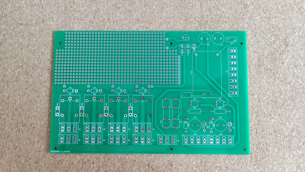 | 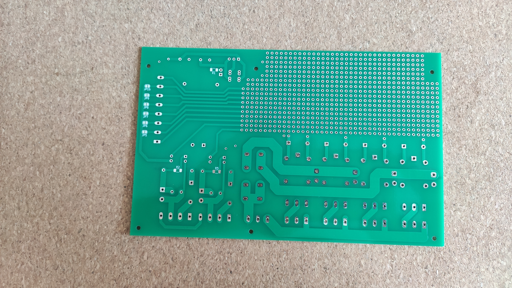 |
|---|---|
| Front | Back |
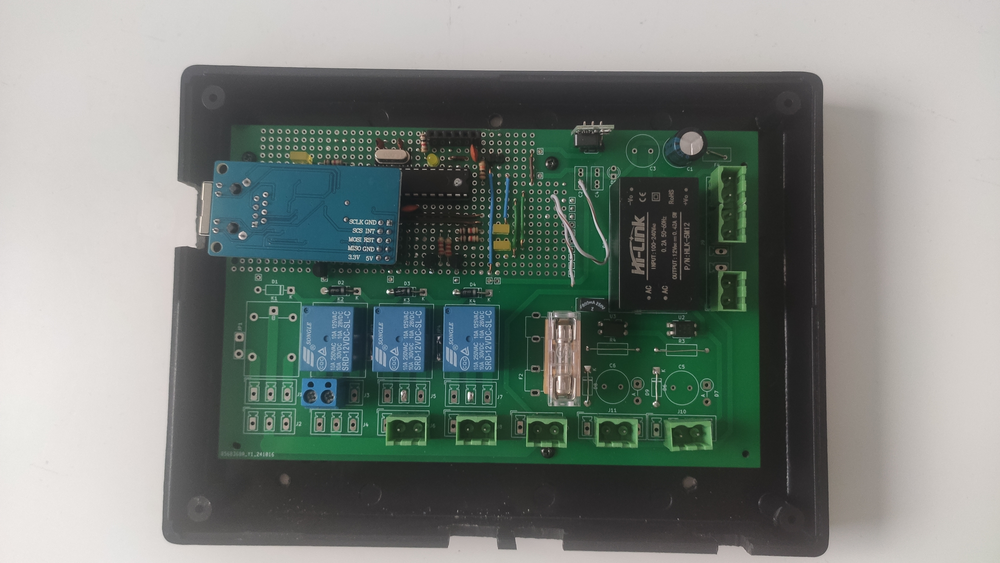 | 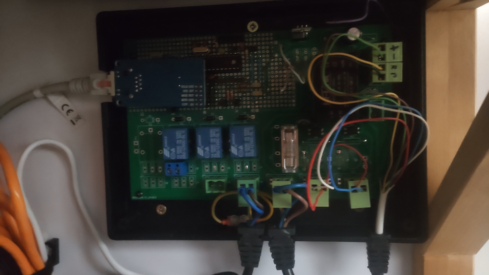 |
| Footprint | Dry contact output | Wet contact output (AC voltage out) |
|---|---|---|
| Kn_DRY (closer to relay) | Populate | Do not populate |
| Kn_230VAC (closer to edge) | Do not populate | Populate |
| KN_WET jumper | Do not populate | Populate using ~1mm^2 wire |
If you are using wet contact output(s), remember to populate F2 or F3 by fuse holder and provide a proper fuse. Remember to select proper amperage based on fuse rate and wiring
If you would like to use eg. NPN or MOSFET-N transistor to drive relay coils and supply it from Hi-Link supply voltage output:
Like above, but short COM_RELAY to 5V net
If you would like to use PNP or MOSFET-P transistors to drive relay coils:
| Footprint | Dry contact (positive) | Dry contact (negative) | Wet contact (low voltage) | Wet contact (AC voltage) |
|---|---|---|---|---|
| J10/J11 | Solder 2-pole terminal to pins 1-2 (left), short pins 3-4 | Solder 2-pole terminal to pins 3-4 (right), short pins 1-2 | Solder 2-pole terminal to pins 2-3 (middle) | Solder 2-pole terminal to pins 2-3 (middle) |
| D6/D8 | Short | Short | Short | Populate |
| R3/R4 | Short | Short | Short | Populate |
| C4/C6 | Do not populate | Do not populate | Do not populate | Populate |
| D7/D9 | Do not populate | Do not populate | Do not populate | Populate |
For all cases:
Short pins 1 and 3 of U1
| Qty | Value | Footprint | References |
|---|---|---|---|
| 18 | TestPoint | Connector_Pin:Pin_D0.7mm_L6.5mm_W1.8mm_FlatFork | TP1, TP2, TP4, TP6, TP10, TP11, TP12, TP13, TP14, TP15, TP16, TP17, TP19, TP20, TP21, TP22 +2 |
| 12 | , , , , , , , , , , , | ||
| 6 | MountingHole | MountingHole:MountingHole_2.2mm_M2 | H1, H2, H3, H4, H5, H6 |
| 6 | ~ | Jumper:SolderJumper-2_P1.3mm_Open_RoundedPad1.0x1.5mm | JP5, JP6, JP7, JP8, JP9, JP10 |
| 4 | 1N4007 | Diode_THT:D_DO-41_SOD81_P10.16mm_Horizontal | D1, D2, D3, D4 |
| 4 | C_Polarized | Capacitor_THT:C_Radial_D10.0mm_H20.0mm_P5.00mm | C1, C3, C5, C6 |
| 4 | G5LE-1 | Relay_THT:Relay_SPDT_Omron-G5LE-1 | K1, K2, K3, K4 |
| 2 | 100k/3W | Resistor_THT:R_Axial_DIN0309_L9.0mm_D3.2mm_P15.24mm_Horizontal | R3, R4 |
| 2 | 1k | Resistor_SMD:R_1206_3216Metric_Pad1.30x1.75mm_HandSolder | R2, R5 |
| 2 | 5v1 | Diode_THT:D_DO-15_P5.08mm_Vertical_AnodeUp | D7, D9 |
| 2 | C | Capacitor_THT:C_Rect_L7.0mm_W3.5mm_P2.50mm_P5.00mm | C2, C4 |
| 2 | D | Diode_THT:D_DO-41_SOD81_P10.16mm_Horizontal | D6, D8 |
| 2 | PC817 | Package_DIP:DIP-4_W7.62mm | U2, U3 |
| 1 | AC IN | Connector_Phoenix_MC_HighVoltage:PhoenixContact_MCV_1,5_3-G-5.08_1x03_P5.08mm_Vertical | J0 |
| 1 | HLK-5M12 | Converter_ACDC:Converter_ACDC_HiLink_HLK-5Mxx | PS1 |
| 1 | IN1_WET | Connector_Phoenix_MC_HighVoltage:PhoenixContact_MCV_1,5_4-G-5.08_1x04_P5.08mm_Vertical | J10 |
| 1 | IN2_WET | Connector_Phoenix_MC_HighVoltage:PhoenixContact_MCV_1,5_4-G-5.08_1x04_P5.08mm_Vertical | J11 |
| 1 | INT | Fuse:Fuse_BelFuse_0ZRE0005FF_L8.3mm_W3.8mm | F1 |
| 1 | INT_LV | Fuse:Fuse_BelFuse_0ZRE0005FF_L8.3mm_W3.8mm | F4 |
| 1 | IO | Connector_Phoenix_MC_HighVoltage:PhoenixContact_MCV_1,5_8-G-5.08_1x08_P5.08mm_Vertical | J9 |
| 1 | K12 | Fuse:Fuseholder_Clip-5x20mm_Keystone_3512_Inline_P23.62x7.27mm_D1.02x1.57mm_Horizontal | F2 |
| 1 | K1_230VAC | Connector_Phoenix_MC_HighVoltage:PhoenixContact_MCV_1,5_3-G-5.08_1x03_P5.08mm_Vertical | J2 |
| 1 | K1_DRY | Connector_Phoenix_MC_HighVoltage:PhoenixContact_MCV_1,5_3-G-5.08_1x03_P5.08mm_Vertical | J1 |
| 1 | K1_WET | TestPoint:TestPoint_2Pads_Pitch5.08mm_Drill1.3mm | JP1 |
| 1 | K2_230VAC | Connector_Phoenix_MC_HighVoltage:PhoenixContact_MCV_1,5_3-G-5.08_1x03_P5.08mm_Vertical | J4 |
| 1 | K2_DRY | Connector_Phoenix_MC_HighVoltage:PhoenixContact_MCV_1,5_3-G-5.08_1x03_P5.08mm_Vertical | J3 |
| 1 | K2_WET | TestPoint:TestPoint_2Pads_Pitch5.08mm_Drill1.3mm | JP2 |
| 1 | K34 | Fuse:Fuseholder_Clip-5x20mm_Keystone_3512_Inline_P23.62x7.27mm_D1.02x1.57mm_Horizontal | F3 |
| 1 | K3_230VAC | Connector_Phoenix_MC_HighVoltage:PhoenixContact_MCV_1,5_3-G-5.08_1x03_P5.08mm_Vertical | J6 |
| 1 | K3_DRY | Connector_Phoenix_MC_HighVoltage:PhoenixContact_MCV_1,5_3-G-5.08_1x03_P5.08mm_Vertical | J5 |
| 1 | K3_WET | TestPoint:TestPoint_2Pads_Pitch5.08mm_Drill1.3mm | JP3 |
| 1 | K4_230VAC | Connector_Phoenix_MC_HighVoltage:PhoenixContact_MCV_1,5_3-G-5.08_1x03_P5.08mm_Vertical | J8 |
| 1 | K4_DRY | Connector_Phoenix_MC_HighVoltage:PhoenixContact_MCV_1,5_3-G-5.08_1x03_P5.08mm_Vertical | J7 |
| 1 | K4_WET | TestPoint:TestPoint_2Pads_Pitch5.08mm_Drill1.3mm | JP4 |
| 1 | L7805 | Package_TO_SOT_THT:TO-92L_Inline_Wide | U1 |
| 1 | POWER ON | LED_THT:LED_D3.0mm | D5 |
| 1 | R | Resistor_SMD:R_1206_3216Metric_Pad1.30x1.75mm_HandSolder | R1 |
The 90 most common of 91 parts.

markstory/ursa-minor-keyboard
Design and schematics for the ursaminor keyboard


It measures 163.8 × 102.9 mm and has 2 copper layers, 1.6 mm thick.
91 parts, built around the HLK-5M12, L7805, K12 and K34. The full list of its parts is on this page, with links to each part's symbol and footprint where PCBKit's library has them.
From the hbiedka/unister-controller-pcb repository on GitHub, at the commit this page was made from: the board is unister.kicad_pcb and its schematic unister.kicad_sch. PCBKit opens the board in the browser, with nothing to install.
Its repository states no licence, so its author keeps all rights: ask hbiedka before reusing the design.