2 layers173 × 122.5 mm

 haydonryan/dell-fan-proxy21
An Arduino based Fan proxy to provide more control over 15th Generation Dell PowerEdge Servers
Dell fan is an open-source printed circuit board by haydonryan, from the haydonryan/dell-fan-proxy repository on GitHub. It is a 2-layer board of 101.6 × 53.3 mm with 49 parts on 40 nets, routed with 241 tracks and 0 vias.
Its parts include 12 resistors, 12 connectors and 1 diode.
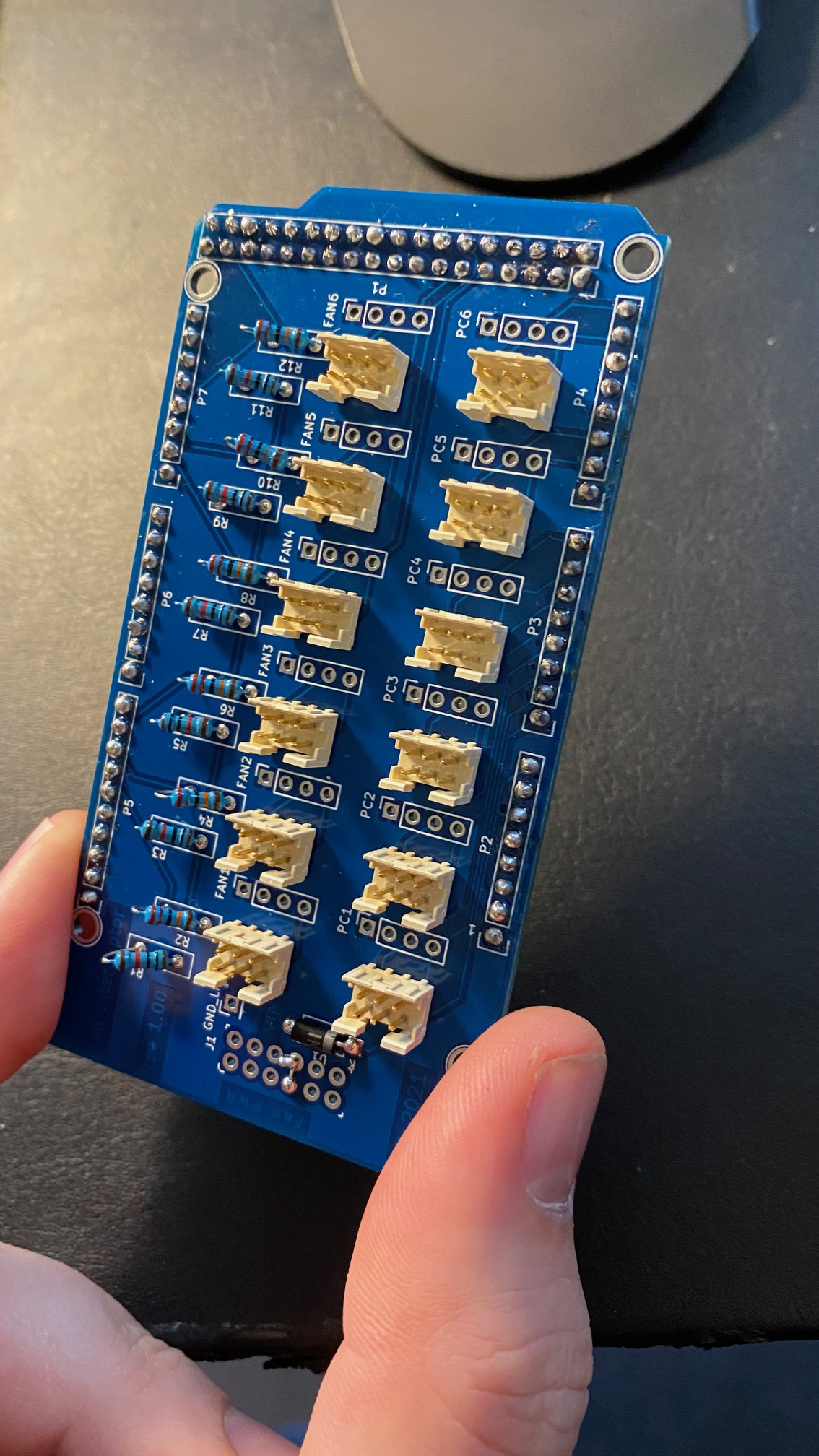

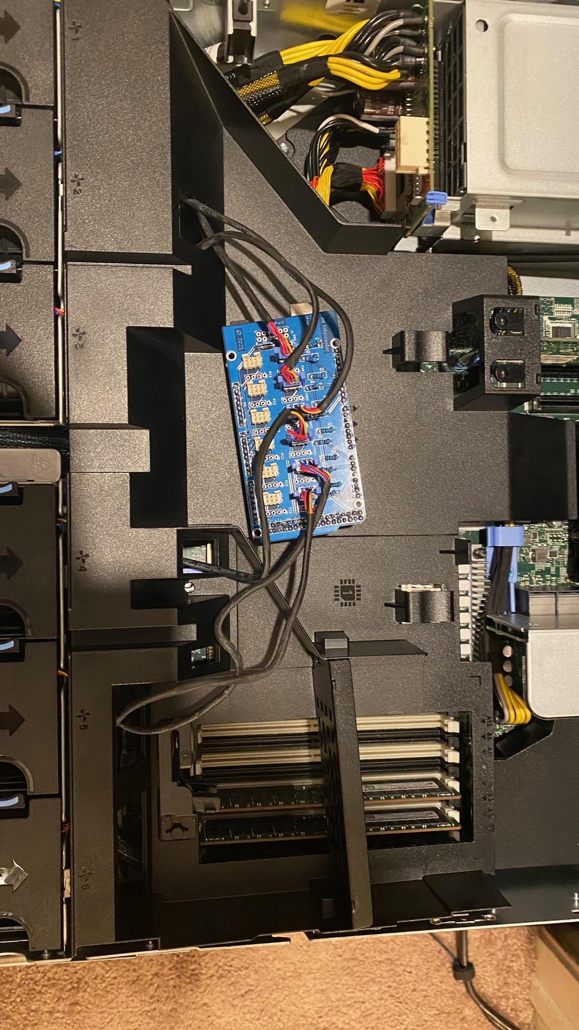
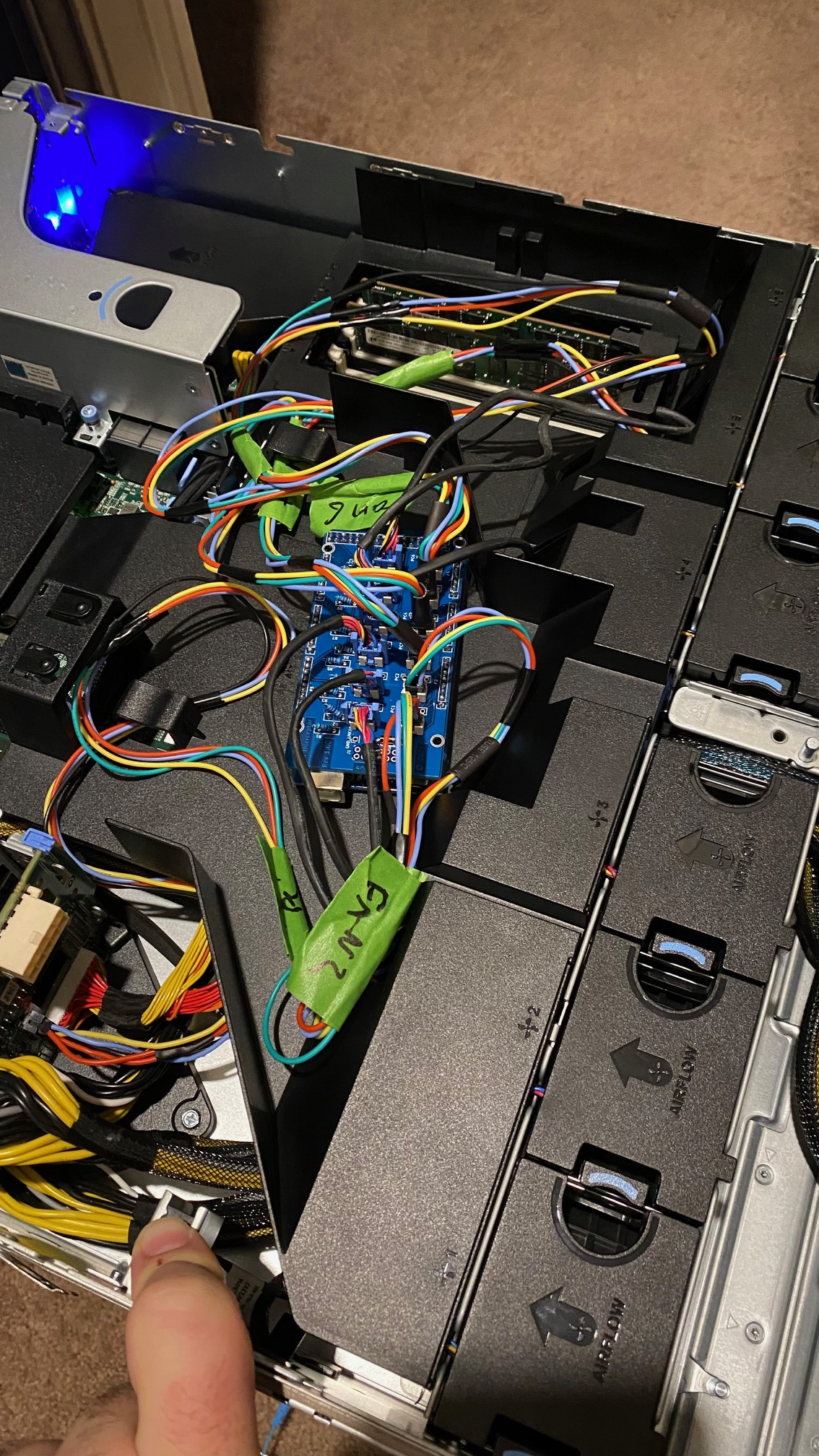
Arduino Mega Fan Controller Sheild For R7515, R540 non hot swap fans.
I run an R7515 in my homelab. It's in a separate room upstairs (from my office) with the door open, I can hear it from my office downstairs. It makes the room unusable that it sits in.
At 43% FAN, I can barely hear it from downstairs, 35% is really not too bad, up close.
The minimum fan speed and therefore noise is designed for a datacenter next to other heat generating servers with no noise contstraints, not a room in a house. Plus I've got some non dell hardware( like many others do in homelabs) that the idrac controller doesn't know how to talk to, so the idrac just ramps the fans up to compensate for that one device.
I also noticed that at idle (which the machine sits 90% of the time) there is a 3 degree C differential between inlet and outlet temp, with the cpu being nice and cool.
Dell support told me I'm not using the server for it's use case (Datacenter usage) - They're correct.
Don't want to modify the firmware (it's signed anyways)
Thought this would be an interesting project tom get more into electronics and control boards.
As these machines come out of primary service in datacenters people are going to want to lab them - let's give them the power to do that!
Will void your warranty
Could cause your server to overheat
Improper connection of fans can short out your motherboard!!!
No responsibility taken for damaged hardware, loss of income, etc.
6 Molex 2.00mm 2 Row, 6 Position Rectangular Receptical (Part # 0511100660) ~80c each https://www.digikey.com/en/products/detail/molex/0511100660/1144838?s=N4IgTCBcDaIOoFkCMAOArAdgwWgHIBEQBdAXyA
36 Molex Connector Socket 24-30AWG Crimp Gold (Part # 0503948054) 5c each https://www.digikey.com/en/products/detail/molex/0503948054/2404822?s=N4IgTCBcDaIAwFY4GYCcAWAHI9IC6AvkA
6 Amphenol ICC Conenctor Through Header Vert 6 Ppos 2.00mm (Part # 98414-G06-06LF) https://www.digikey.com/en/products/detail/amphenol-icc-fci/98414-G06-06LF/1535247?s=N4IgTCBcDaIGwAYCcBaAzHMAOFA5AIiALoC%2BQA
1 Arduino Mega
24 AWG hookup wire - 5 colors preferred, but just be careful if you don't have different colors Cheaper on Amazon (https://www.amazon.com/CBAZYTM-Stranded-Flexible-Silicone-Electric/dp/B073RD76QD/ref=sr_1_22?dchild=1&keywords=24%2BAWG&qid=1606865665&s=hi&sr=1-22&th=1)
6 TMP36 Temperature Sensors?? ~$1.50 https://www.digikey.com/en/products/detail/analog-devices-inc/TMP36GT9Z/820404
Shrink wrap for wires
By measuring and pulling pins out of the fan, I was able to determine that the pins (with the plastic nib up, facing away from you in the order:
1   2   3
4   5   6
That the Wires are:
Arduino Pin Register
source: http://astro.neutral.org/arduino/arduino-pwm-pins-frequency.shtml
Checked the continuity - on the new server board - there's a common 12v rail AND common 12v ground. This means that I can easily check the fan project using the bench power supply.
So far so good on the server. Printed U shaped spacers to save the cables for fans 1-3. Definitely prefer to do this over not having anything pushing the top up.
I did find that only fan 3 has 12v power when powered off, the rest must be switched somewhere in the motherboard.
Cable lengths:
Max length shrink tubing at the arduino end: 1-1.5cm
I've been testing this during summer and noticed that as the inlet temperature approaches the limit "for this configuration" the fans ramp significantly. This is clearly a preventative reaction rather than a reactive one. Also ensuring that the hardware that is in the server is "compatilbe" aka listed on the compatabilty matrix certainly helps to reduce the speed of the fans.
Have been running my server 24/7 for two years now with no ill effects. No hardware failures, and just less noise. It's not perfect and fans seem to surge slightly vs stay flat consistently. It's not too big of an issue and could probably be adjusted by increasing the time the fans are averaged. Very happy with how this project is running.
Put some shrink tubing on the 12v wire on the loop and the main wire before putting the terminal into the block. Stray 12v is SUPER bad. Cut the terminal off the tape but leave the small bit of tape on for holding it steady. put the terminal into the 1.3mm crimp size first all the way up to the tape - it should hold itself in there - making it easier to feed in the cable(s).
Make sure to crimp the actual insulation. Don't have the wire come out too far as mounting this, the pins will potentially pus the pin out if there's not enough space. https://www.youtube.com/watch?v=Ta55NTSBLN0
Do the dual power lead crimp first (it's the hardest)
It would be much safer to map the fan speed returned to idrac from the detected speed of the fan, not the requested rpm. That way if a fan fails, then idrac will throw a fault.
Starting point: https://www.youtube.com/watch?v=UJK2JF8wOu8
Replacement Fan: https://www.itcreations.com/product/119156
Standard 4 pin fan pinout https://allpinouts.org/pinouts/connectors/motherboards/motherboard-cpu-4-pin-fan/
https://github.com/Max-Sum/HP-fan-proxy/blob/master/hp_fan.ino
https://www.reddit.com/r/homelab/comments/8wbogx/my_attempt_at_creating_a_circuit_board_that/
https://www.reddit.com/r/homelab/comments/beuks5/silencing_the_hp_dl380_for_good/
Setting the interrupt priority: https://www.youtube.com/watch?v=H3o08WE0zEI
Delta Fan Datasheet for similar fan: https://www.mouser.com/datasheet/2/632/dele_s_a0011169984_1-2290125.pdf
https://homeservershow.com/forums/topic/7294-faking-the-fan-signal/
https://forum.arduino.cc/t/problem-measuring-4-pin-fan-rpm/666804/6
http://www.benripley.com/diy/arduino/three-ways-to-read-a-pwm-signal-with-arduino/
| Qty | Value | Footprint | References |
|---|---|---|---|
| 6 | 10k | Resistor_THT:R_Box_L13.0mm_W4.0mm_P9.00mm | R1, R3, R5, R7, R9, R11 |
| 6 | 220k | Resistor_THT:R_Box_L13.0mm_W4.0mm_P9.00mm | R2, R4, R6, R8, R10, R12 |
| 6 | To FAN | Connector_PinHeader_2.00mm:PinHeader_2x03_P2.00mm_Vertical | FAN_1, FAN_2, FAN_3, FAN_4, FAN_5, FAN_6 |
| 6 | To Fan | Connector_PinSocket_2.54mm:PinSocket_1x04_P2.54mm_Vertical | FAN1, FAN2, FAN3, FAN4, FAN5, FAN6 |
| 6 | To PC | Connector_PinHeader_2.00mm:PinHeader_2x03_P2.00mm_Vertical | PC_1, PC_2, PC_3, PC_4, PC_5, PC_6 |
| 6 | To PC | Connector_PinSocket_2.54mm:PinSocket_1x04_P2.54mm_Vertical | PC1, PC2, PC3, PC4, PC5, PC6 |
| 4 | CONN_01X01 | Socket_Arduino_Mega:Arduino_1pin | P8, P10, P11, P13 |
| 2 | Analog | Socket_Arduino_Mega:Socket_Strip_Arduino_1x08 | P3, P4 |
| 1 | 1N4007 | Diode_THT:D_A-405_P7.62mm_Horizontal | D1 |
| 1 | Communication | Socket_Arduino_Mega:Socket_Strip_Arduino_1x08 | P7 |
| 1 | Digital | Socket_Arduino_Mega:Socket_Strip_Arduino_2x18 | P1 |
| 1 | PWM | Socket_Arduino_Mega:Socket_Strip_Arduino_1x08 | P6 |
| 1 | PWM | Socket_Arduino_Mega:Socket_Strip_Arduino_1x10 | P5 |
| 1 | Power | digikey-footprints:PinHeader_6x2_P2.54mm_Horizontal | J1 |
| 1 | Power | Socket_Arduino_Mega:Socket_Strip_Arduino_1x08 | P2 |
It measures 101.6 × 53.3 mm and has 2 copper layers, 1.6 mm thick.
49 parts. The full list of its parts is on this page, with links to each part's symbol and footprint where PCBKit's library has them.
From the haydonryan/dell-fan-proxy repository on GitHub, at the commit this page was made from: the board is Arduino Shield/dell-fan.kicad_pcb. PCBKit opens the board in the browser, with nothing to install.
Its repository states no licence, so its author keeps all rights: ask haydonryan before reusing the design.


benkrasnow/DSKY_EL_replica
Schematic, PCB layout, mechanical CAD, and firmware to create a replica of the DSKY with electroluminescent display


