
2 layers60 × 30 mm
Controller
google/mozc-devices
Circuit diagrams and firmware source code for Gboard DIY keyboards
11 parts3kApache-2.0

 Hawk453/Rectifier_AC_to_DC
PCB Design of a Full Wave Rectifier
Rectifier AC to DC is an open-source printed circuit board by Hawk453, from the Hawk453/Rectifier_AC_to_DC repository on GitHub, published under the MIT licence. It is a 2-layer board of 90 × 62 mm with 11 parts on 9 nets, routed with 25 tracks and 2 vias.
It is built around the TY-304P. Its parts include 3 connectors, 2 capacitors, 2 diodes and 2 switches.
This repository contains the KiCAD project files for a full-wave rectifier circuit. The circuit is designed to convert an AC input to a DC output and features a switchable filter capacitance to demonstrate the effect of different capacitor values on the rectified signal.
The circuit takes an AC signal, passes it through a transformer (TR1), and then rectifies it using a full-wave bridge rectifier (diodes D1, D2, D3, D4). The rectified DC signal is then smoothed by a filter capacitor (C1 or C2). A switch (SW1) allows the user to select either the 100uF capacitor (C1) or the 1000uF capacitor (C2) to see the difference in filtering. The output is available at a BNC connector (J2).
J1).SW1 and SW2) to select the desired filter capacitance:
C1)C2)J2).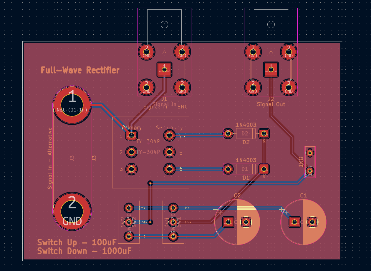
This project is licensed under the LICENSE file.
| Qty | Value | Footprint | References |
|---|---|---|---|
| 2 | 1N4003 | Diode_THT:D_DO-41_SOD81_P10.16mm_Horizontal | D1, D2 |
| 2 | SW_SPDT | Switches_Footprints:SPDT_Slide_Switch_L12mm_W6mm_Pitch4mm | SW1, SW2 |
| 1 | 1000uF | PCM_Capacitor_THT_US_AKL:CP_Radial_D12.5mm_P5.00mm | C2 |
| 1 | 100uF | PCM_Capacitor_THT_US_AKL:CP_Radial_D12.5mm_P5.00mm | C1 |
| 1 | 1KΩ | PCM_Resistor_THT_AKL:R_Box_L8.4mm_W2.5mm_P5.08mm | 1KΩ |
| 1 | Signal In | Connector_Coaxial:BNC_TEConnectivity_1478035_Horizontal | J1 |
| 1 | Signal In - Alternative | Connector:Banana_Jack_2Pin | J3 |
| 1 | Signal Out | Connector_Coaxial:BNC_TEConnectivity_1478035_Horizontal | J2 |
| 1 | TY-304P | Transformers_Footprints:TY_304P_Triad | TY-304P |
google/mozc-devices
Circuit diagrams and firmware source code for Gboard DIY keyboards


FrameworkComputer/ExpansionCards
Reference designs and documentation to create Expansion Cards for the Framework Laptop

hoglet67/RGBtoHDMI
Bare-metal Raspberry Pi project that provides pixel-perfect sampling of Retro Computer RGB/YUV video and conversion to HDMI

hackclub/OnBoard
💡 Join 1,000 teenagers and make your first PCB with a $100 grant!


tardate/LittleArduinoProjects
a collection of "Little Electronic & Arduino Projects", most involving electronics or an Arduino in one way or another!

basilfx/TRADFRI-Hacking
Hacking IKEA TRÅDFRI products, such as light bulbs, window blinds and other accessories.
It measures 90 × 62 mm and has 2 copper layers, 1.6 mm thick.
11 parts, built around the TY-304P. The full list of its parts is on this page, with links to each part's symbol and footprint where PCBKit's library has them.
From the Hawk453/Rectifier_AC_to_DC repository on GitHub, at the commit this page was made from: the board is Rectifier_AC_to_DC.kicad_pcb and its schematic Rectifier_AC_to_DC.kicad_sch. PCBKit opens the board in the browser, with nothing to install.
Its repository publishes it under the MIT licence: you may reuse it on that licence's terms (keep the author's notice, and for a copyleft licence share your changes alike).