4 layers74.1 × 99.3 mm

 haru135790/mp3213
ここでは、vialを使用するとできることについて簡単に説明します。(詳細な操作方法等についてはネットで検索するか、後述の参考記事をご覧ください) 1. キーマップの変更 - キーに割り当てられた機能を自由に変更できます。 - キーボードに実際にあるキーだけでなく、メディアキー(音楽の再生/停止など)や、特殊キー(画面の明るさ調整など)も割り当て可能です。 - 複数のキーを同時に押すショートカット(例…
Mp321 is an open-source printed circuit board by haru135790, from the haru135790/mp321 repository on GitHub. It is a 2-layer board of 91 × 55 mm with 39 parts on 49 nets, routed with 243 tracks and 49 vias.
It is built around the AMS1117-3.3 and X49SM8MSD2SC. Its parts include 12 capacitors, 10 switches, 8 resistors, 2 ICs and 2 connectors. It belongs with the STM32 boards of this library.


mp321は、コンパクトな左手デバイスです。名刺サイズの基板に6つのキーとロータリーエンコーダーが搭載されています。 vialを使用してキー割り当てを自由に変更できます。
本機のキー割り当ては「vial」というソフトウェアを使用することで変更できます。 vialにはwebブラウザ版とアプリケーション版があり、ブラウザ版はChrome、アプリ版はWindows,macOS,Linuxで動作します。 また、2025/10/21時点で、vialは日本語対応していません。ご注意ください。
ここでは、vialを使用するとできることについて簡単に説明します。(詳細な操作方法等についてはネットで検索するか、後述の参考記事をご覧ください)
vialの詳細な使用方法については、こちらの記事がおすすめです。
X(Twitter): https://x.com/haru1357900
mp321は初期状態では次のようなキー設定となっています。
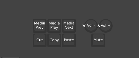
mp321についているノブ(ロータリーエンコーダー)は、vial上では右回転と左回転、押し込みがそれぞれ分かれて表示されています。
| Qty | Value | Footprint | References |
|---|---|---|---|
| 8 | 0.1uF | Capacitor_SMD:C_0603_1608Metric | C1, C2, C3, C6, C7, C8, C9, C10 |
| 6 | SW_Push | PCM_Switch_Keyboard_Cherry_MX:SW_Cherry_MX_PCB_1.00u | SW3, SW4, SW5, SW6, SW7, SW8 |
| 4 | MountingHole | MountingHole:MountingHole_3.2mm_M3 | H1, H2, H3, H4 |
| 3 | 10k | Resistor_SMD:R_0603_1608Metric | R2, R4, R6 |
| 2 | 30pF | Capacitor_SMD:C_0603_1608Metric | C4, C5 |
| 2 | 4.7uF | Capacitor_SMD:C_0603_1608Metric | C11, C12 |
| 2 | 5.1k | Resistor_SMD:R_0603_1608Metric | R3, R5 |
| 2 | BOOT | Button_Switch_SMD:SW_Push_1P1T_XKB_TS-1187A | SW1, SW2 |
| 1 | 1.5k | Resistor_SMD:R_0603_1608Metric | R7 |
| 1 | 1M | Resistor_SMD:R_0603_1608Metric | R8 |
| 1 | 20k | Resistor_SMD:R_0603_1608Metric | R1 |
| 1 | AMS1117-3.3 | Package_TO_SOT_SMD:SOT-223-3_TabPin2 | U1 |
| 1 | RotaryEncoder | Rotary_Encoder:RotaryEncoder_Alps_EC11E-Switch_Vertical_H20mm | SW9 |
| 1 | STM32F103C8Tx | Package_QFP:LQFP-48_7x7mm_P0.5mm | U2 |
| 1 | SW_SPDT | Haru13579:SW_Push_1P1T-MP_NO_Horizontal_Alps_SSAJ120100 | SW10 |
| 1 | Serial | Connector_PinHeader_2.54mm:PinHeader_1x04_P2.54mm_Vertical | J1 |
| 1 | USB_C_Plug_USB2.0 | Connector_USB:USB_C_Receptacle_GCT_USB4105-xx-A_16P_TopMnt_Horizontal | P1 |
| 1 | X49SM8MSD2SC | Crystal:Crystal_SMD_HC49-SD | Y1 |
It measures 91 × 55 mm and has 2 copper layers, 1.6 mm thick.
39 parts, built around the AMS1117-3.3 and X49SM8MSD2SC. The full list of its parts is on this page, with links to each part's symbol and footprint where PCBKit's library has them.
From the haru135790/mp321 repository on GitHub, at the commit this page was made from: the board is KiCad/mp_321.kicad_pcb and its schematic KiCad/mp_321.kicad_sch. PCBKit opens the board in the browser, with nothing to install.
Its repository states no licence, so its author keeps all rights: ask haru135790 before reusing the design.

Phil-CIA/Development-Station-Power-Supply
3 channel bench supply with current and voltage plotting

mahmoud-elghamry/thermocouple
This directory is a self-contained KiCad 10 project. It does not share files with, and must not be confused with, the single-channel board in hardware/single-channel/.

Aykut-Gencer-KARACA/BLDC-Driver
PCB'nin Blender'da hazırlanmış 3D render'ı · tam çözünürlüklü video için görsele tıklayın


DownUnderCTF/Challenges_2024_Public
Files + Solutions for DownUnderCTF 2024 Challenges


Phil-CIA/Solar-Project-200w
Solar Project 200W is a prototype-first hardware and firmware effort for a 200W-class solar charging system built around a 4S LiFePO4 battery domain.