2 layers156.5 × 67.5 mm
NixieScanDisplay
profdc9/NixieClock
A Nixie clock that uses IN-14 tubes and very generic components that can be easily sourced.
106 parts10

 hansrune/RelayBoardX3
3x relay board used for garage door control and ventilator motors
RelayBoardX3 is an open-source printed circuit board by hansrune, from the hansrune/RelayBoardX3 repository on GitHub. It is a 2-layer board of 85.1 × 63.5 mm with 54 parts on 38 nets, routed with 256 tracks and 0 vias.
It is built around the L7805 and 2N2222A. Its parts include 16 connectors, 14 resistors, 8 diodes, 3 capacitors and 3 transistors. It belongs with the home automation and IoT boards and the ESP32 boards of this library.


Work in progress / still a prototype...
A DYI 3x relay board based on ESP32c3. This is a multi purpose board used for:
Garage doors - controlling dual garage doors and control use of external switchesVentilator / 1-phase small motor 1-2-3 speed control.This board is tested with ESPhome and ESPEasy firmware (build instructions below), and is easily used with home automation systems that support MQTT auto discovery, the native Home Assistant API, and the many controllers that ESPEasy supports
Some of the main features and benefits
Each of the four valve outputs has a LED indicator at the back of the PCB
The schematic diagram is available here. The KiCad EDA project is in the same folder
| PIN | Capabilty | Function |
|---|---|---|
| GPIO2 | Acticve low output | LED D8 - not used |
| GPIO3 | Input with pull-up | J7 pin 2 |
| GPIO4 | Input with pull-up | J7 pin 1 |
| GPIO5 | Active high output | Relay 1 |
| GPIO6 | Active high output | Relay 2 |
| GPIO7 | I2C pulled up | SDL |
| GPIO8 | I2C pulled up | SDA |
| GPIO9 | Active low out | LED D8 - status |
| GPIO10 | Active high output | Relay 3 |
| GPIO20 | RX / 1-wire | Serial or 1-wire sensor or ultrasound |
| GPIO21 | TX / 1-wire | Serial or 1-wire sensor or ultrasound |
This project uses my KiCad-lib-ESP32 repository as a git submodule. To check this out, use the following:
git clone --recurse-submodules https://github.com/hansrune/RelayBoardX4.git This project uses the Seed Studio XIAO ESP32C3 RISC-V module. This tiny device has proven to be more reliable than most ESP8266 modules used in earlier versions. This module also comes with an IPX connector for connecting an external antenna, and is delivered with a simple external antenna for good range. This device is also EMI shielded and certified.
Any available 12V DC power supply delivering 500mA or more should do for the control board. You will need to add the total power draw for the relays
There are many options and possible pinouts for DC-DC converters for the 12V to 5V conversion. A linear regulator (L7805) will need a heatsink, so a DC-DC converter is recommended.
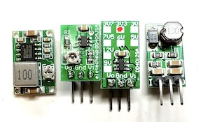
The MOSFETs need a low Vgs trigger voltage, i.e. well under 3V on full load. I have used Si2302/N025P for the N-channel, SOT-23 package.
Resistors are 0805 size. Screw terminals are 3.5mm, which is a tight fit when ferrules are being used.
For more information, use this KiCad BOM
Soldering a prototype by hand is possible if you have a steady hand and a small solder iron tip. A microscope is recommended to inspect the solder joints properly.
Recommend to do the SMD parts first, then other components.
You should test at least the following before adding the ESP32 module:
ESPHome firmware can be set up from this ESPHome configuration repository using the test_relayx3_garage.yaml or test_relayx3_motor.yaml file as a template
Follow the README for instructions on what you will likely want to change.
By default, MQTT auto discovery is being used. This should work out of the box with Home Assistant, Domoticz and other that support Home Assistant MQTT Auto Discovery
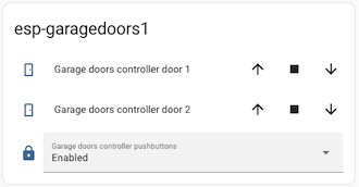
In Home Assistant, the garage door controls can look like this:
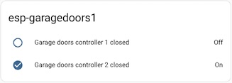
... and the closed state end stop sensors:
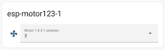
In Home Assistant, the device has this simple selector:
ESPEasy can be used with a number of different controllers / home automation systms. A custom firmware build description is available here
ESPEasy requires many settings. For configuration settings and rule files, you can upload the below sets of files. Please make sure to change name, unit number, controller IP addresses, NTP, syslog host and latitude/longitude. This configuration uses both a MQTT controller and a Domoticz controller. Change to what you need.
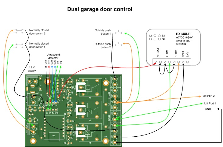
This dual garage door setup uses a pulse driven elevator, and has end stop switches for the closed position. There is no end stops for the open position, meaning that the open state simply reflects not closed.
A RX-Multi receiver is used in parallel with the relay board. This is operated by remote control units from a car.
We have outdoor push buttons to operate the garage doors. These are disabled via relay #1 when our home alarm state is away or night. The power on state is that these buttons are enabled.
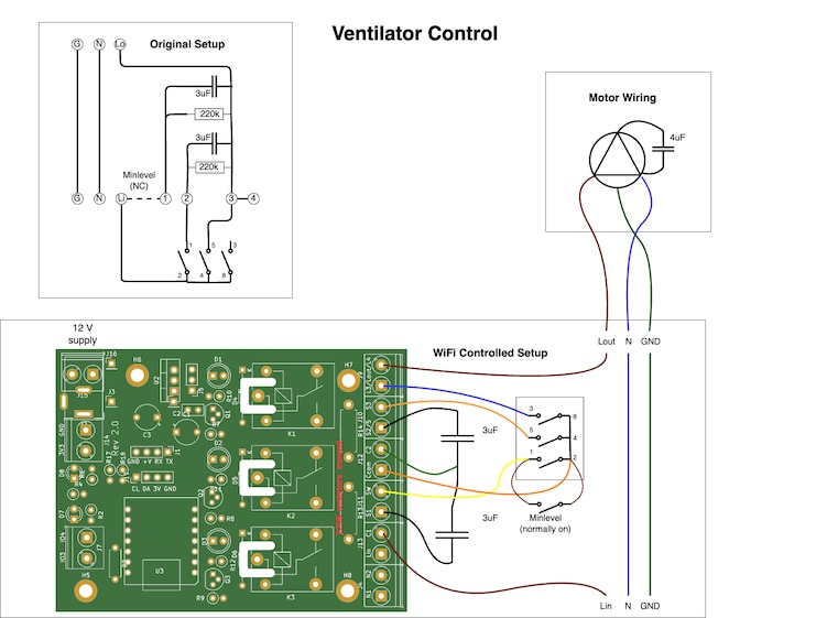
This setup is a simple 1-2-3 speed motor control for a ventilator. Can work in parallel with a 1-2-3 switch, where you will get the highest speed selected via contoller or switch.
This project is licensed under the GNU General Public License v3.0 for the software, CERN-OHL-W for the hardware, and CC BY-SA for the documentation and ideas.
| Qty | Value | Footprint | References |
|---|---|---|---|
| 9 | Screw_Terminal_01x02 | TerminalBlock_Phoenix:TerminalBlock_Phoenix_PT-1,5-2-5.0-H_1x02_P5.00mm_Horizontal | J4, J7, J9, J10, J11, J12, J13, J14, J15 |
| 4 | MountingHole_Pad | MountingHole:MountingHole_3.2mm_M3_ISO14580_Pad | H5, H6, H7, H8 |
| 3 | 10k | Resistor_THT:R_Axial_DIN0207_L6.3mm_D2.5mm_P2.54mm_Vertical | R4, R17, R18 |
| 3 | 1N4007 | Diode_THT:D_DO-34_SOD68_P12.70mm_Horizontal | D4, D5, D6 |
| 3 | 1k | Resistor_THT:R_Axial_DIN0207_L6.3mm_D2.5mm_P2.54mm_Vertical | R7, R8, R9 |
| 3 | 2N2222A | Package_TO_SOT_THT:TO-92 | Q1, Q2, Q3 |
| 3 | 330 | Resistor_THT:R_Axial_DIN0207_L6.3mm_D2.5mm_P2.54mm_Vertical | R10, R11, R12 |
| 3 | Conn_01x01_Male | Connector_PinHeader_2.54mm:PinHeader_1x01_P2.54mm_Vertical | J3, J8, J16 |
| 3 | LED | LED_THT:LED_D5.0mm_Clear | D1, D2, D3 |
| 3 | SANYOU_SRD_Form_C | LOCAL1:Relay_SPDT_SANYOU_SRD_CutOut | K1, K2, K3 |
| 2 | 10uF | Capacitor_THT:CP_Radial_Tantal_D6.0mm_P5.00mm | C1, C3 |
| 2 | 220k | Resistor_THT:R_Axial_DIN0411_L9.9mm_D3.6mm_P12.70mm_Horizontal | R13, R14 |
| 2 | 270 | Resistor_THT:R_Axial_DIN0207_L6.3mm_D2.5mm_P2.54mm_Vertical | R1, R2 |
| 2 | Conn_01x04_Male | Connector_PinHeader_2.54mm:PinHeader_1x04_P2.54mm_Vertical | J1, J17 |
| 2 | LED | LED_THT:LED_D3.0mm_Clear | D7, D8 |
| 1 | 100nF | Capacitor_THT:C_Disc_D5.0mm_W2.5mm_P2.50mm | C2 |
| 1 | 10k | Resistor_THT:R_Axial_DIN0207_L6.3mm_D2.5mm_P7.62mm_Horizontal | R3 |
| 1 | Barrel_Jack | LOCAL1:BarrelJack1 | J2 |
| 1 | Conn_01x03_Male | Connector_PinHeader_2.54mm:PinHeader_1x03_P2.54mm_Vertical | J5 |
| 1 | L7805 | Package_TO_SOT_THT:TO-220-3_Vertical | U2 |
| 1 | SeedStudio XIAO ESP32 C3 THT | LOCAL1:XIAO_ESP32C3_THT | U3 |
| 1 | SolderJumper_3_Open | Jumper:SolderJumper-3_P1.3mm_Open_Pad1.0x1.5mm_NumberLabels | JP1 |
profdc9/NixieClock
A Nixie clock that uses IN-14 tubes and very generic components that can be easily sourced.

hansrune/BallValveController
Ball valve controller for irrigation, water automations and leak prevention. Supports CR05 feedback wiring. Based on ESP32c3. ESPEasy and ESPHome based firmware build instructions included


jastikai/Embedded-System-Project
Repository for Embedded System Project course of University of Oulu, Spring 2024.


lynchaj/rhyophyre
Single Board Computer featuring Zilog Z180 processor and NEC µPD7220 Graphics Display Controller
It measures 85.1 × 63.5 mm and has 2 copper layers, 1.6 mm thick.
54 parts, built around the L7805 and 2N2222A. The full list of its parts is on this page, with links to each part's symbol and footprint where PCBKit's library has them.
From the hansrune/RelayBoardX3 repository on GitHub, at the commit this page was made from: the board is KiCad/RelayBoardX3.kicad_pcb and its schematic KiCad/RelayBoardX3.kicad_sch. PCBKit opens the board in the browser, with nothing to install.
Its repository states no licence, so its author keeps all rights: ask hansrune before reusing the design.