2 layers50 × 23.2 mm
Analog
hoglet67/RGBtoHDMI
Bare-metal Raspberry Pi project that provides pixel-perfect sampling of Retro Computer RGB/YUV video and conversion to HDMI
32 parts1kGPL-3.0

 hansliss/atari_keypad1
A 12-key keypad for the joystick port, based on the Atari 2600 keypad
Atari keypad is an open-source printed circuit board by hansliss, from the hansliss/atari_keypad repository on GitHub, published under the BSD-2-Clause licence. It is a 2-layer board of 67.6 × 99.3 mm with 32 parts on 20 nets, routed with 359 tracks and 0 vias.
Its parts include 12 diodes, 12 switches, 3 resistors and 1 connector. It belongs with the keyboards and input and retro computing and games boards of this library.
A 12-key keypad for the joystick port, based on the Atari 2600 keypad
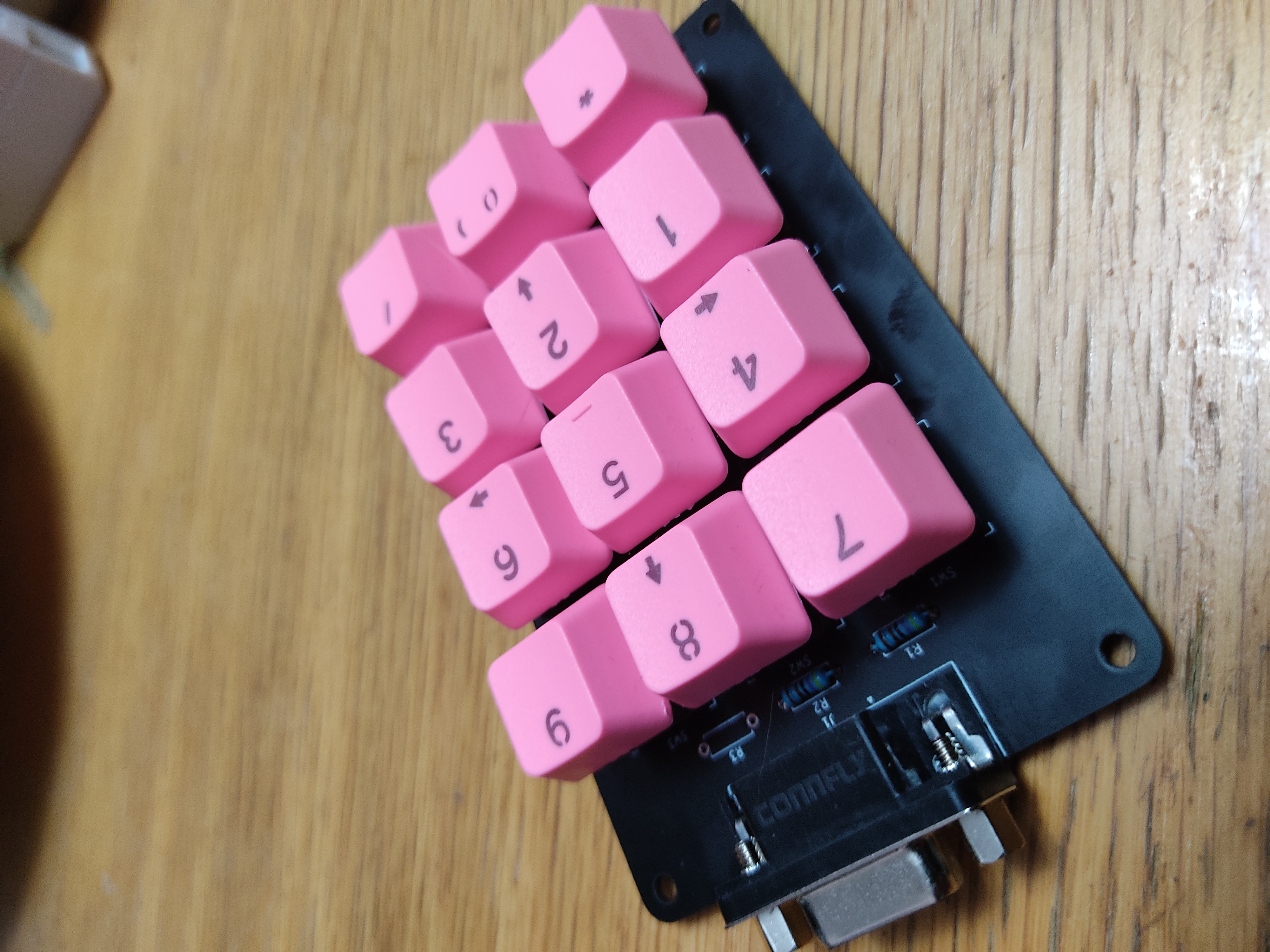
The keypad uses Kailh sockets for Cherry MX-compatible keyswitches, and is meant to be used with a 3d-printed box, including a faceplate to keep the switches in place. This box has not been designed yet.
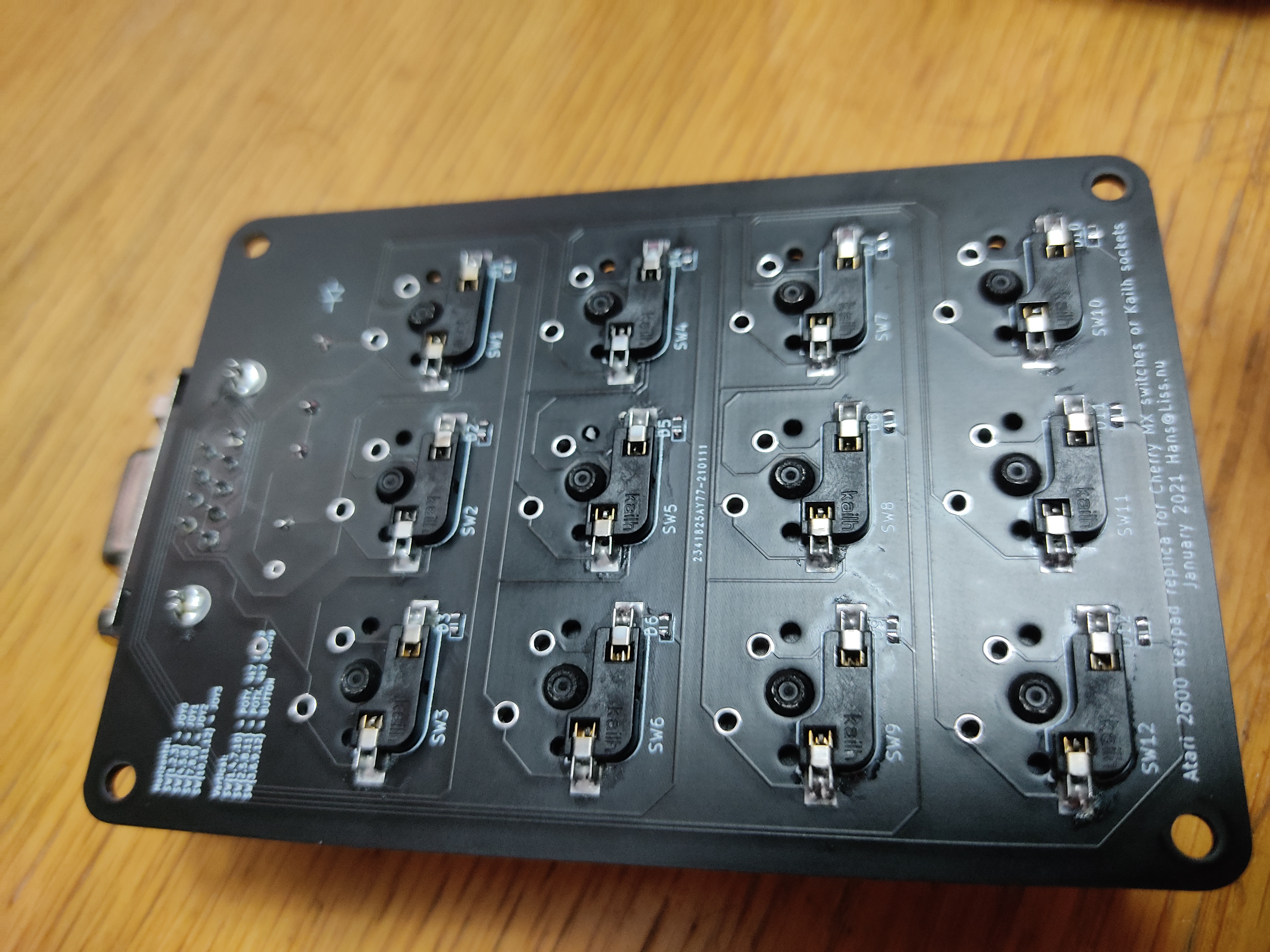
The keypad has anti-ghosting diodes on all keys. There are three pull-up resistors, one for each column. The original keypad only included the first two resistors, and as far as I know, the third one is not needed.
The design includes a PCB-mounted DB-9 female connector. You can use this with a straight, fully connected DB-9 male-to-female cable to connect the keypad to a computer or console, or you can just solder cables to the solder pads if you prefer that.
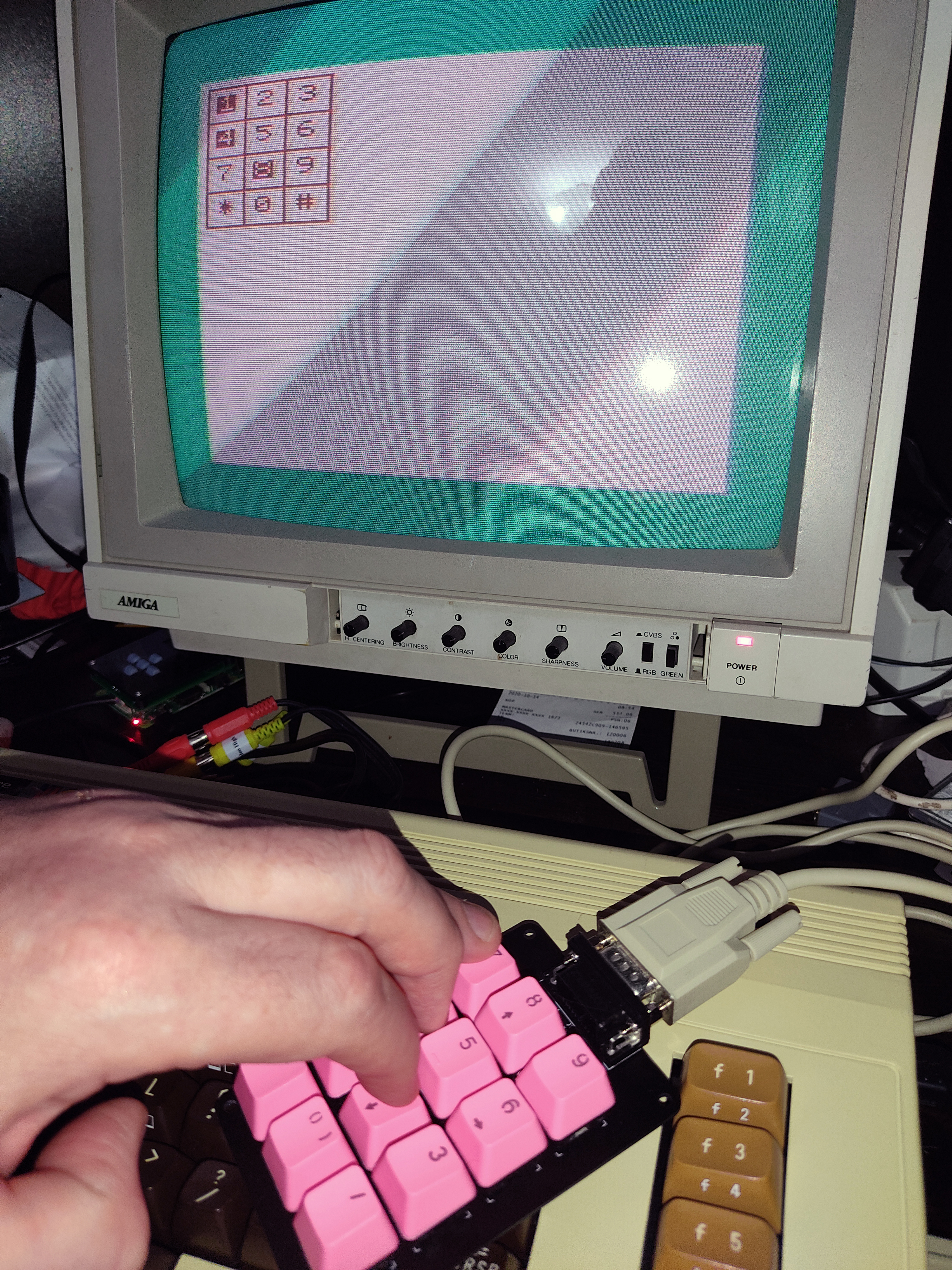
Included is also VIC-20 code for scanning the keypad. It includes full N-key rollover and produces two bytes of bits, one bit for each key. Debouncing is done by delaying keypress events until they have been seen by at least two scanning cycles.
There is a second machine code program that calls the poller and then "unpacks" the bit fields into a series of individual bytes, one for each key. This is because BASIC turns out to be breathtakingly slow at this kind of bit-mangling.
There are two BASIC programs, one that uses just the main subroutine and does the bit unpacking itself, and another on that uses the "reorg" subroutine to to get unpacked bytes. The second one is a little bit faster.
Finally, there is a machine code version of the BASIC code, which better demonstrates the keypad at full speed.
| Qty | Value | Footprint | References |
|---|---|---|---|
| 12 | D | Diodes_SMD:D_0603 | D1, D2, D3, D4, D5, D6, D7, D8, D9, D10, D11, D12 |
| 3 | 4k7 | Resistors_THT:R_Axial_DIN0207_L6.3mm_D2.5mm_P7.62mm_Horizontal | R1, R2, R3 |
| 1 | DB9_Female | Connectors_DSub:DSUB-9_Female_Horizontal_P2.77x2.84mm_EdgePinOffset4.94mm_Housed_MountingHolesOffset7.48mm | J1 |
| 1 | SW_0 | keyswitches:Kailh_socket_MX_optional_compatible | SW11 |
| 1 | SW_1 | keyswitches:Kailh_socket_MX_optional_compatible | SW1 |
| 1 | SW_2 | keyswitches:Kailh_socket_MX_optional_compatible | SW2 |
| 1 | SW_3 | keyswitches:Kailh_socket_MX_optional_compatible | SW3 |
| 1 | SW_4 | keyswitches:Kailh_socket_MX_optional_compatible | SW4 |
| 1 | SW_5 | keyswitches:Kailh_socket_MX_optional_compatible | SW5 |
| 1 | SW_6 | keyswitches:Kailh_socket_MX_optional_compatible | SW6 |
| 1 | SW_7 | keyswitches:Kailh_socket_MX_optional_compatible | SW7 |
| 1 | SW_8 | keyswitches:Kailh_socket_MX_optional_compatible | SW8 |
| 1 | SW_9 | keyswitches:Kailh_socket_MX_optional_compatible | SW9 |
| 1 | SW_Hash | keyswitches:Kailh_socket_MX_optional_compatible | SW12 |
| 1 | SW_Star | keyswitches:Kailh_socket_MX_optional_compatible | SW10 |
The 28 most common of 32 parts.
hoglet67/RGBtoHDMI
Bare-metal Raspberry Pi project that provides pixel-perfect sampling of Retro Computer RGB/YUV video and conversion to HDMI

hackclub/OnBoard
💡 Join 1,000 teenagers and make your first PCB with a $100 grant!


octosavvi/ESPKey
Wiegand data logger, replay device and micro door-controller

zmaker/arduino_cookbook
gli sketch del nuovo progetto Arduino Cookbook e dei video di YouTube

murexrobotics/electrical
Highly integrated electronics design and printed circuit boards (PCBs) for the MATE ROV Competition. Attempt the impossible.

swharden/AVR-projects
A collection of standalone AVR projects written in C

hardenedlinux/cheap-pcb
Cheap PCB: Better understanding the current status of hardware supply chain
It measures 67.6 × 99.3 mm and has 2 copper layers, 1.6 mm thick.
32 parts. The full list of its parts is on this page, with links to each part's symbol and footprint where PCBKit's library has them.
From the hansliss/atari_keypad repository on GitHub, at the commit this page was made from: the board is Atari_keypad.kicad_pcb. PCBKit opens the board in the browser, with nothing to install.
Its repository publishes it under the BSD-2-Clause licence: you may reuse it on that licence's terms (keep the author's notice, and for a copyleft licence share your changes alike).