2 layers39.1 × 39.9 mm
Nebula
Thecactusman0/Nebula-openwatch
Nebula is a ESP32 based smartwatch that features a rotating bezel encoder
85 parts4
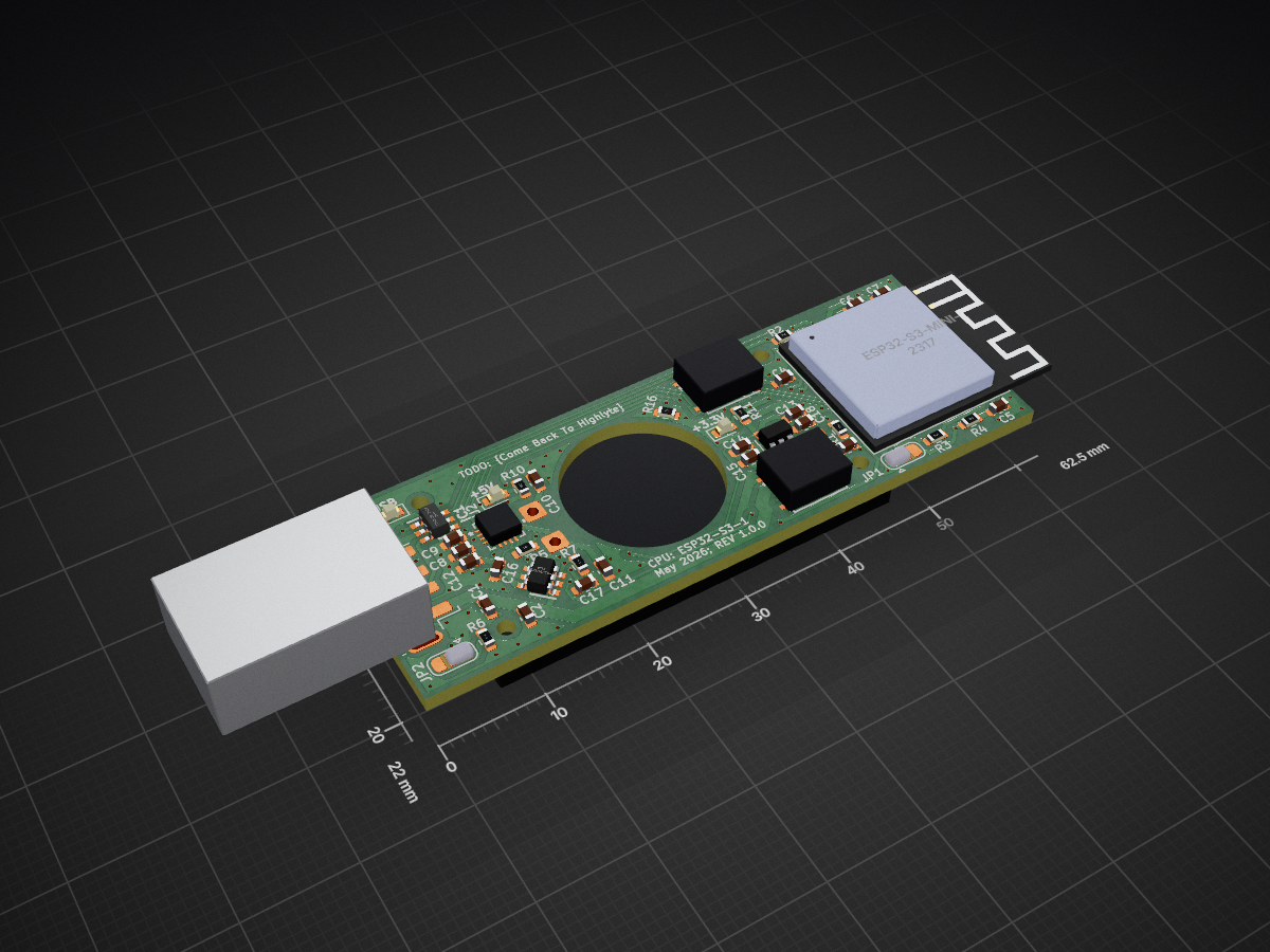
 HAdamCode/usb-audio-device
KiCad 10 project for the board the firmware in ../firmware/ runs on.
Usb audio device is an open-source printed circuit board by HAdamCode, from the HAdamCode/usb-audio-device repository on GitHub, published under the MIT licence. It is a 2-layer board of 62.5 × 22 mm with 52 parts on 63 nets, routed with 449 tracks and 138 vias.
It is built around the ESP32-S3-MINI-1-N8, MAX98357AETE+T and USBLC6-2SC6. Its parts include 18 capacitors, 16 resistors, 7 diodes, 5 ICs and 2 switches. It belongs with the audio and music boards and the ESP32 boards of this library.


KiCad 10 project for the board the firmware in ../firmware/ runs on.
USB_Audio_Device.kicad_pro     project
USB_Audio_Device.kicad_sch     schematic
USB_Audio_Device.kicad_pcb     layout
USB_Audio_Device-BOM.csv       bill of materials
schematic_export.pdf           schematic, no KiCad needed
fp-lib-table / sym-lib-table   library tables
_USB_Audio_Device.pretty/ project-local footprints| MCU | ESP32-S3-MINI-1 (U1), native USB, no USB-UART bridge |
| Amplifier | MAX98357A (U2), I2S class-D, gain set by JP2 |
| Amp power | TPS22917 load switch (U3) on the +5 V rail, gated by EN_SPKR |
| Regulator | TLV70233 (U4), 3.3 V |
| ESD | USBLC6-2SC6 (IC1) on the USB data pair |
| Speaker | LS1, 8 Ω, two through-holes |
| Buttons | SW1 → EN (reset), SW2 → IO0 (bootloader, doubles as the user button) |
| LEDs | D1–D3 rail indicators (VUSB / +5V / +3V3), D4–D7 user LEDs on GPIO |
| Connector | USB-A plug — the board goes into the host, not a cable |
Full net-to-GPIO mapping is in ../firmware/main/board.h,
annotated against this schematic.
These came from the working copy of the project and are worth knowing about before you open it on a different machine.
1. The symbol library isn't here. sym-lib-table points at an absolute Windows
path:
(lib (name "_USB_Audio_Device") (type "KiCad")
     (uri "D:/USB_Audio_Device_PCB/Components/_USB_Audio_Device.kicad_sym") ...)
The schematic still opens and renders correctly — KiCad caches every symbol
definition inside the .kicad_sch itself — but the library shows as missing, and
"Update Symbols from Library" won't work. To fix it, copy
_USB_Audio_Device.kicad_sym into this folder and change that uri to:
${KIPRJMOD}/_USB_Audio_Device.kicad_symfp-lib-table already uses ${KIPRJMOD}, so footprints resolve fine as-is.
2. One footprint is absent. USB_A_Molex_48037-2200_Horizontal is referenced by
J2 in the BOM but its .kicad_mod file wasn't in the set I was given. The PCB will
open — the layout stores its own copy of every placed footprint — but the library
entry is missing. Drop the file into _USB_Audio_Device.pretty/ when you find it.
3. 3D models point at D:/. Every footprint references a .step/.iges under
D:/USB_Audio_Device_PCB/Components/. The 3D viewer will show those parts as blank.
Harmless for fabrication; only matters if you want a rendering.
KiCad resolves a footprint by filename, so each .kicad_mod here is named after the
footprint it declares — e.g. the file declaring (footprint "SOT95P280X145-6N_(USB_ESD)")
is saved as SOT95P280X145-6N_(USB_ESD).kicad_mod. If you re-export from your working
copy, keep that convention or the library won't resolve.
One suggestion from writing the firmware: add a dedicated user button on a spare GPIO. SW1 is hardwired to the module's EN pin so it can only reset, which leaves SW2 (on IO0, a strapping pin) as the only button software can read. That works, but it means holding the button while the board powers up drops it into flashing mode instead of playing. GPIO21, 34, 35, 36 and 37 are all unused and unstrapped.
| Qty | Value | Footprint | References |
|---|---|---|---|
| 7 | 10k | Resistor_SMD:R_0603_1608Metric | R1, R2, R3, R4, R7, R8, R16 |
| 7 | LED | LED_SMD:LED_0603_1608Metric | D1, D2, D3, D4, D5, D6, D7 |
| 6 | 100nF | Capacitor_SMD:C_0603_1608Metric | C1, C3, C4, C6, C8, C15 |
| 5 | 75 | Resistor_SMD:R_0603_1608Metric | R11, R12, R13, R14, R15 |
| 3 | 10uF | Capacitor_SMD:C_0603_1608Metric | C9, C16, C18 |
| 2 | 1M | Resistor_SMD:R_0603_1608Metric | R5, R6 |
| 2 | 1uF | Capacitor_SMD:C_0603_1608Metric | C5, C13 |
| 2 | 200 | Resistor_SMD:R_0603_1608Metric | R9, R10 |
| 2 | 220pF | Capacitor_SMD:C_0603_1608Metric | C10, C11 |
| 2 | 5uF | Capacitor_SMD:C_0603_1608Metric | C2, C14 |
| 1 | 1900pF | Capacitor_SMD:C_0603_1608Metric | C17 |
| 1 | 22uF | Capacitor_SMD:C_0603_1608Metric | C7 |
| 1 | 47uF | Capacitor_SMD:C_0603_1608Metric | C12 |
| 1 | Boot Debug | Jumper:SolderJumper-3_P1.3mm_Bridged12_RoundedPad1.0x1.5mm | JP1 |
| 1 | Bootloader | _USB_Audio_Device:SMT_FS_BUTTON | SW2 |
| 1 | ESP32-S3-MINI-1 | _USB_Audio_Device:ESP32-S2-MINI-1 | U1 |
| 1 | Gain Selection | Jumper:SolderJumper-3_P1.3mm_Open_RoundedPad1.0x1.5mm | JP2 |
| 1 | MAX98357AETE+T | _USB_Audio_Device:21-0136I_T1633-4_MXM-M | U2 |
| 1 | Reset | _USB_Audio_Device:SMT_FS_BUTTON | SW1 |
| 1 | Speaker | _USB_Audio_Device:speaker_mount | LS1 |
| 1 | TLV70233_SOT23-5 | Package_TO_SOT_SMD:SOT-23-5 | U4 |
| 1 | TPS22917DBVT | _USB_Audio_Device:DBV0006_N_Inrush_Limiter | U3 |
| 1 | USBLC6-2SC6 | _USB_Audio_Device:SOT95P280X145-6N_(USB_ESD) | IC1 |
| 1 | USB_A | _USB_Audio_Device:USB_A_Molex_48037-2200_Horizontal | J2 |
It measures 62.5 × 22 mm and has 2 copper layers, 1.6 mm thick.
52 parts, built around the ESP32-S3-MINI-1-N8, MAX98357AETE+T and USBLC6-2SC6. The full list of its parts is on this page, with links to each part's symbol and footprint where PCBKit's library has them.
From the HAdamCode/usb-audio-device repository on GitHub, at the commit this page was made from: the board is hardware/USB_Audio_Device.kicad_pcb and its schematic hardware/USB_Audio_Device.kicad_sch. PCBKit opens the board in the browser, with nothing to install.
Its repository publishes it under the MIT licence: you may reuse it on that licence's terms (keep the author's notice, and for a copyleft licence share your changes alike).
Thecactusman0/Nebula-openwatch
Nebula is a ESP32 based smartwatch that features a rotating bezel encoder


Guilleloma/Furby-GPT
This project transforms a 1998 Furby into an interactive and advanced desktop assistant using a Raspberry Pi W. It incorporates OpenAI and Whisper for natural language processing, primarily relying on Google Cloud Text…


skrmsh/skirmish-hardware
Skirmish Hardware © 2022-2023 by Ole Lange is licensed under CC BY-NC-SA 4.0. To view a copy of this license, visit http://creativecommons.org/licenses/by-nc-sa/4.0/

GuzziFlipFlops/ESP32-Walkie-Talkie
An open source ESPNOW based walkie talkie with a 600 meter tested distance, with an OLED and multiple buttons to interact with

sini6a/internet-radio-speaker
An open-source ESP32 Internet Radio Player with simple programming, USB charging, and on-the-go capability using a single-cell Li-ion battery.