Skip to the content
PCBKitNew board
2 layers50 × 51 mmPrismo reader, the printed circuit board in 3D

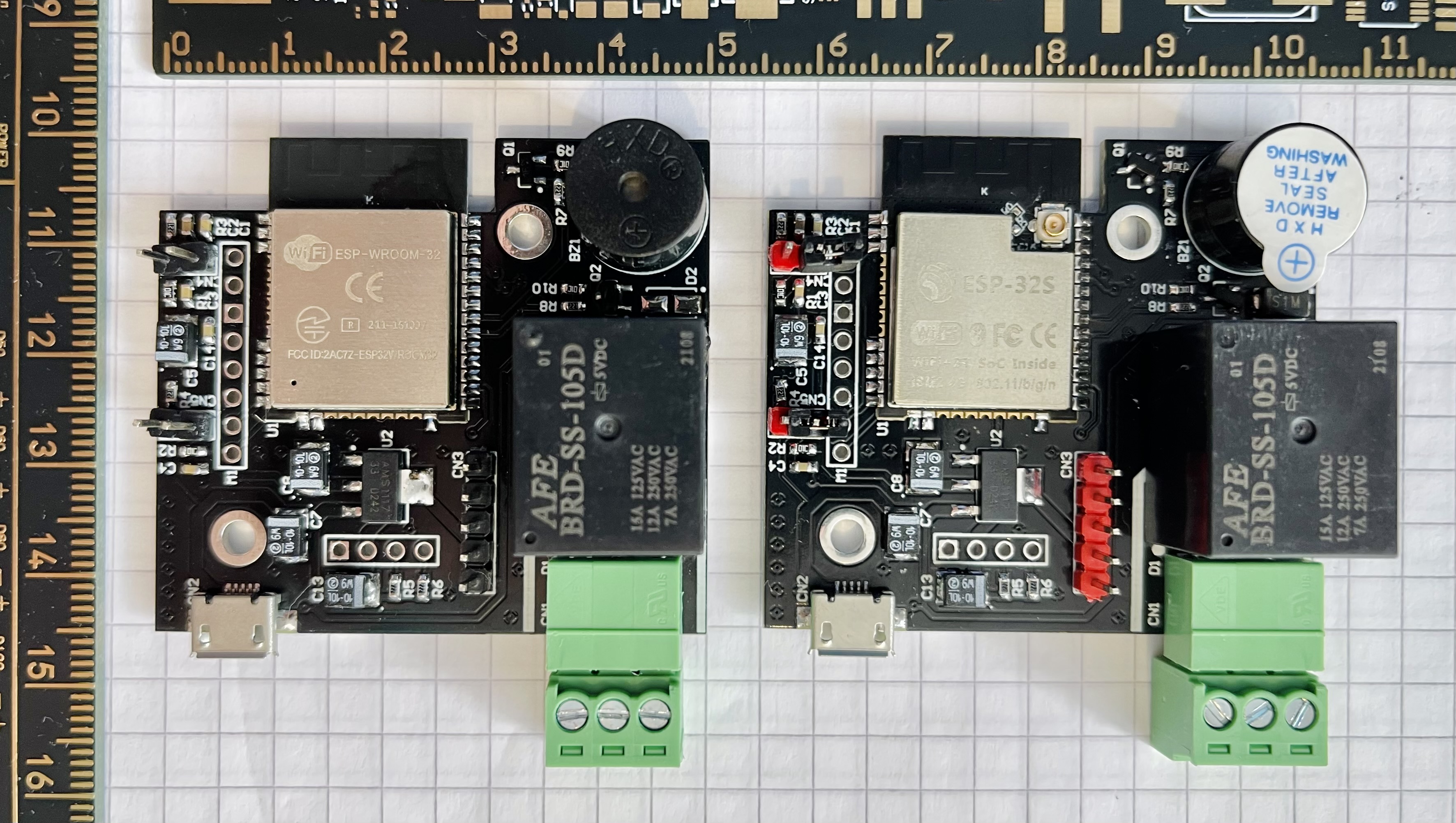
RFID readers of Prismo access management system

Size
50 × 51 mm
Copper layers
2
Thickness
1.6 mm
Parts
48
Nets
72
Pads
224
Tracks, vias
610, 100
Pours
1
Routed
Yes
KiCad
KiCad 9.0 (file 20241229)
Created
13 Feb 2020
Updated
15 May 2026

Overview

Prismo reader is an open-source printed circuit board by hacklabkyiv, from the hacklabkyiv/prismo-reader repository on GitHub, published under the GPL-3.0 licence. It is a 2-layer board of 50 × 51 mm with 48 parts on 72 nets, routed with 610 tracks and 100 vias.

It is built around the ESP32-WROOM-32D, AMS1117-2.85 and WS2812B, with the BC847, SP0503BAHTG and US1M among its other parts. Its parts include 13 capacitors, 13 resistors, 6 diodes, 4 connectors and 3 ICs. It belongs with the interfaces and adapters boards and the ESP32 boards of this library.

Main components

6

README

README.md

PRISMO readers

(WIP)

Boards

Protocol description

Flashing instructions

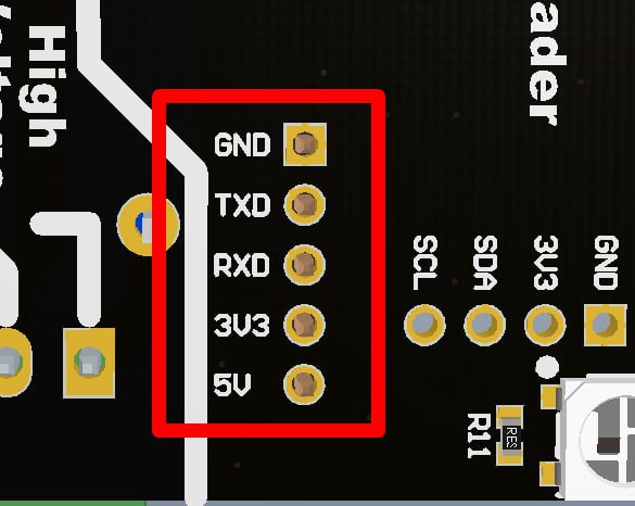
Before any development mode interactions with the board it needs to be connected to a computer. The interface intended for flashing and debugging is UART. Please connect your USB-UART adapter to the pins on the board as shown on the image below:

uart

text
READER  USB-UART
5V  ->  5V
GND ->  GND
RX  ->  TX
TX  ->  RX
optional
3V3 ->  3V3

First of all the information about Micropython and it's installation can be found on their official page: https://micropython.org/download/esp32/

Depending on your prefered OS the USB-UART can be named differently. For example:

  • MacOS /dev/tty.usbserial-1220
  • Ubuntu /dev//dev/ttyUSB0
  • Windows COM1

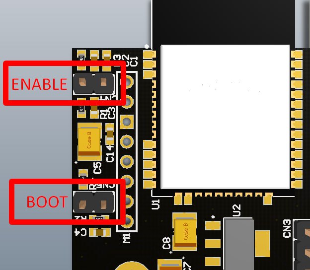
To enter to the flashing mode the board should start with BOOT0 pin pulled to GND. In order to achieve that short and hold BOOT pins, then short and release ENABLE pins and then release BOOT pins.

Boot

The commands also available below:

sh
esptool.py --chip esp32 --port /dev/tty.usbserial-1220 erase_flash
sh
esptool.py --chip esp32 --port /dev/tty.usbserial-1220 --baud 460800 write_flash -z 0x1000 esp32-20230426-v1.20.0.bin

To put source code files on board (ampy)[https://pypi.org/project/adafruit-ampy/] tool is needed. Put all files from src folder to the board one by one.

It is better for the main.py to be the last one.

main.py starts processes which may affect further access to the board by ampy tool If that has happened - please enter to the REPL (picocom is a nice tool for that) mode and remove main.py manually. Use this prompt: import os; os.remove('main.py'). Don't forget to put main.py back in order to be back to normal operation.

sh
ampy -p /dev/tty.usbserial-11210 -b115200 -d4 put boot.py
ampy -p /dev/tty.usbserial-11210 -b115200 -d4 put PN532.py
ampy -p /dev/tty.usbserial-11210 -b115200 -d4 put config.py
ampy -p /dev/tty.usbserial-11210 -b115200 -d4 put main.py

HW test

After flashing your device, you can test your hardware. To do this, uncomment HW_TEST in settings.h file and flash this firmware. In serial monitor, with key is near the RFID frame (baudrate 9600) you should get something like this:

text
------ HW TEST STARTED --------
17:38:34.011 -> ------ HW TEST STARTED --------
17:38:37.001 -> 33384541313932323930304532333845413139323239303045323338454131393232393030453233384541313932323930304532333845413139323239303045323338454131393232393030453233384541
17:38:40.620 -> ------ HW TEST STARTED --------
17:38:43.608 -> ------ HW TEST STARTED --------

Connection test with test server

Comment back HW_TEST in settings.h and specify network settings there.

text
STASSID	- name of your wifi network
STAPSK 	- password to your wifi network
HOST 	- IP address to your test server.
PORT	- Unique port of your reader

In test_server.py choose right MY_IP - IP of machine where test_server.py running and READER_PORT.

Parts

48
QtyValueFootprintReferences
910kResistor_SMD:R_0805_2012Metric_Pad1.20x1.40mm_HandSolderR2, R3, R7, R8, R9, R10, R11, R12, R14
7100nCapacitor_SMD:C_0805_2012Metric_Pad1.18x1.45mm_HandSolderC1, C2, C8, C9, C10, C11, C12
4WS2812BLED_SMD:LED_WS2812B_PLCC4_5.0x5.0mm_P3.2mmD1, D2, D3, D4
310uFCapacitor_Tantalum_SMD:CP_EIA-3216-18_Kemet-A_Pad1.58x1.35mm_HandSolderC4, C5, C13
21uFCapacitor_SMD:C_0805_2012Metric_Pad1.18x1.45mm_HandSolderC6, C7
25.6kResistor_SMD:R_0805_2012Metric_Pad1.20x1.40mm_HandSolderR15, R16
2BC847Package_TO_SOT_SMD:SOT-23Q2, Q3
2MountingHoleMountingHole:MountingHole_3.5mmH1, H2
1100uFCapacitor_Tantalum_SMD:CP_EIA-3528-21_Kemet-B_Pad1.50x2.35mm_HandSolderC3
1220RResistor_SMD:R_0805_2012Metric_Pad1.20x1.40mm_HandSolderR13
122RResistor_SMD:R_0805_2012Metric_Pad1.20x1.40mm_HandSolderR1
12N7002Package_TO_SOT_SMD:SOT-23Q1
1AMS1117-2.85Package_TO_SOT_SMD:SOT-223-3_TabPin2U3
1BuzzerBuzzer_Beeper:Buzzer_Murata_PKMCS0909EBZ1
1CP2102N-Axx-xQFN24Package_DFN_QFN:QFN-24-1EP_4x4mm_P0.5mm_EP2.6x2.6mmU2
1Conn_01x03TerminalBlock_Phoenix:TerminalBlock_Phoenix_PT-1,5-3-3.5-H_1x03_P3.50mm_HorizontalJ1
1ESP32-WROOM-32DRF_Module:ESP32-WROOM-32DU1
1External 5V powerConnector_JST:JST_XH_B2B-XH-A_1x02_P2.50mm_VerticalJ4
1G5LE-1Relay_THT:Relay_SPDT_Omron-G5LE-1K1
1Logout buttonButton_Switch_SMD:SW_SPST_PTS645SW1
1PN532 ConnectorConnector_PinSocket_2.54mm:PinSocket_1x08_P2.54mm_Vertical_SMD_Pin1LeftJ3
1SP0503BAHTPackage_TO_SOT_SMD:SOT-143D6
1US1MDiode_SMD:D_SMAD5
1USB4120-03-C_REVAusb_connector:GCT_USB4120-03-C_REVAJ5

The 47 most common of 48 parts.

Questions

How big is the Prismo reader PCB?

It measures 50 × 51 mm and has 2 copper layers, 1.6 mm thick.

What parts does the Prismo reader use?

48 parts, built around the ESP32-WROOM-32D, AMS1117-2.85, WS2812B and BC847. The full list of its parts is on this page, with links to each part's symbol and footprint where PCBKit's library has them.

Where can I download the Prismo reader KiCad files?

From the hacklabkyiv/prismo-reader repository on GitHub, at the commit this page was made from: the board is hw/rev.3.0/PRISMO-reader.kicad_pcb and its schematic hw/rev.3.0/PRISMO-reader.kicad_sch. PCBKit opens the board in the browser, with nothing to install.

Can I use the Prismo reader design in my own project?

Its repository publishes it under the GPL-3.0 licence: you may reuse it on that licence's terms (keep the author's notice, and for a copyleft licence share your changes alike).

Similar boards

  • 4 layers97.5 × 52 mmMain module, the printed circuit board in 3D

    Main module

    shm-dmitry/auto_close_window

    This IOT project allows you to open and close your window from any smart house. For example - you can setup rules like a "If night and noise greater then expected -> close window" and "Noise reduced -> open window"
    121 parts1Apache-2.0
  • 4 layers144 × 69 mmXray v2, the printed circuit board in 3D

    Xray v2

    shm-dmitry/xray-detector

    V3 version in progress. V2 version details:

    154 parts
  • 2 layers90 × 45 mmEsp32-dalitester, the printed circuit board in 3D

    Esp32-dalitester

    lukasprojects/esp32-dalitester

    Small ESP32 DALI tester for commissioning and maintaining light installations via the DALI bus

    84 parts
  • 2 layers89.2 × 82.6 mmDesktop 50 Pin TopConn, the printed circuit board in 3D

    Desktop 50 Pin TopConn

    BlueSCSI/BlueSCSI-v2

    BlueSCSI v2/Ultra - an open source, open hardware, SCSI emulator using the Pi Pico PR2040 and Pico 2 RP2350

    108 parts459GPL-3.0
  • 2 layers82.1 × 56.3 mmPowerBook, the printed circuit board in 3D

    PowerBook

    daniel-ayers/BlueSCSI-v2

    Snapshot of BlueSCSI/BlueSCSI-v2 for evidential purposes. Not updated.

    95 partsGPL-3.0
  • 2 layers52.6 × 53.3 mmHDB50 External, the printed circuit board in 3D

    HDB50 External

    tachesimazzoca/scsi-adapters

    This repository contains PCB files for SCSI adapters.

    64 parts