
2 layers45 × 45 mm
Aeroq Hardware v3
EnriqueNeyra/Aeroq
An Indoor Air Quality Monitor Powered by ESP32, SCD40, and SEN54
56 parts130
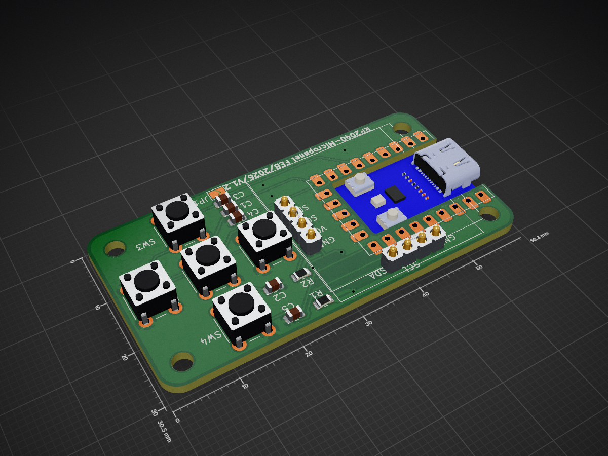
 hackboxguy/usb-hid-display
A firmware for the mcu to acts as an usb-composite-device(hid-iput and ttyACMx serial device)
Usb hid display is an open-source printed circuit board by hackboxguy, from the hackboxguy/usb-hid-display repository on GitHub, published under the GPL-3.0 licence. It is a 2-layer board of 59.3 × 30.5 mm with 20 parts on 23 nets, routed with 136 tracks and 7 vias.
It is built around the 0.1UF 50V 5*11 and RP2040-ZERO. Its parts include 5 capacitors, 5 switches, 2 resistors and 2 ICs. It belongs with the lEDs and displays boards and the RP2040 boards of this library.
A firmware for Raspberry Pi Pico (RP2040) that turns cheap off-the-shelf components (rotary encoder, push buttons, SSD1306 OLED) into a standalone USB micro-panel for embedded Linux devices.
This firmware creates a USB composite device with two interfaces:
/dev/ttyACMx) — The host writes binary commands over this serial port to control the SSD1306 OLED display: draw text, progress bars, set brightness, etc.Together, these two interfaces form a self-contained hardware menu system — physical buttons for input, OLED for output — driven entirely from the host over a single USB cable. No drivers required; the device uses standard USB HID and CDC ACM classes supported by all major operating systems.
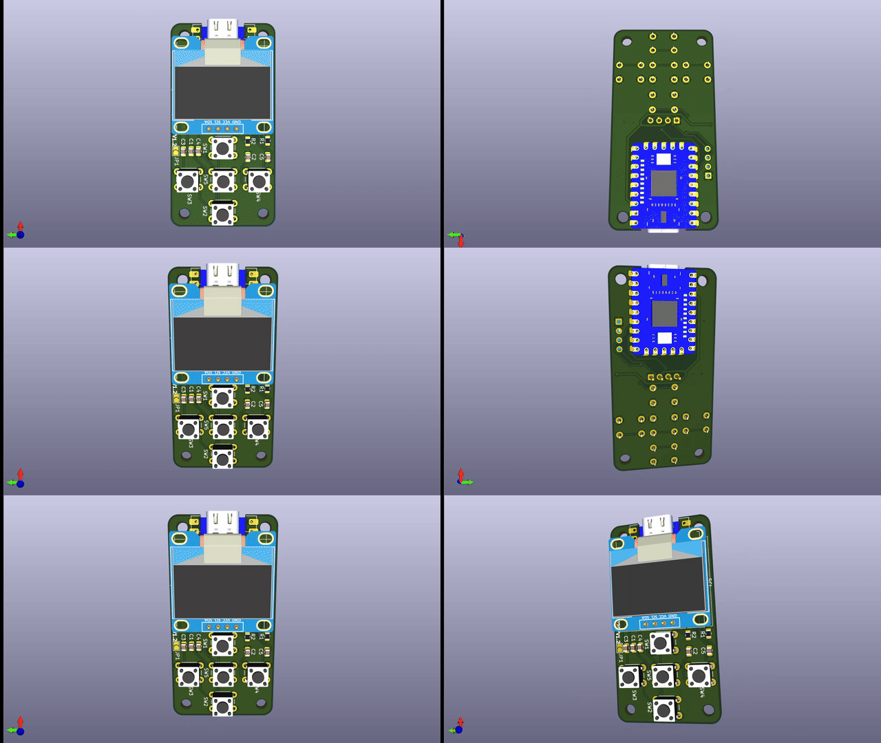
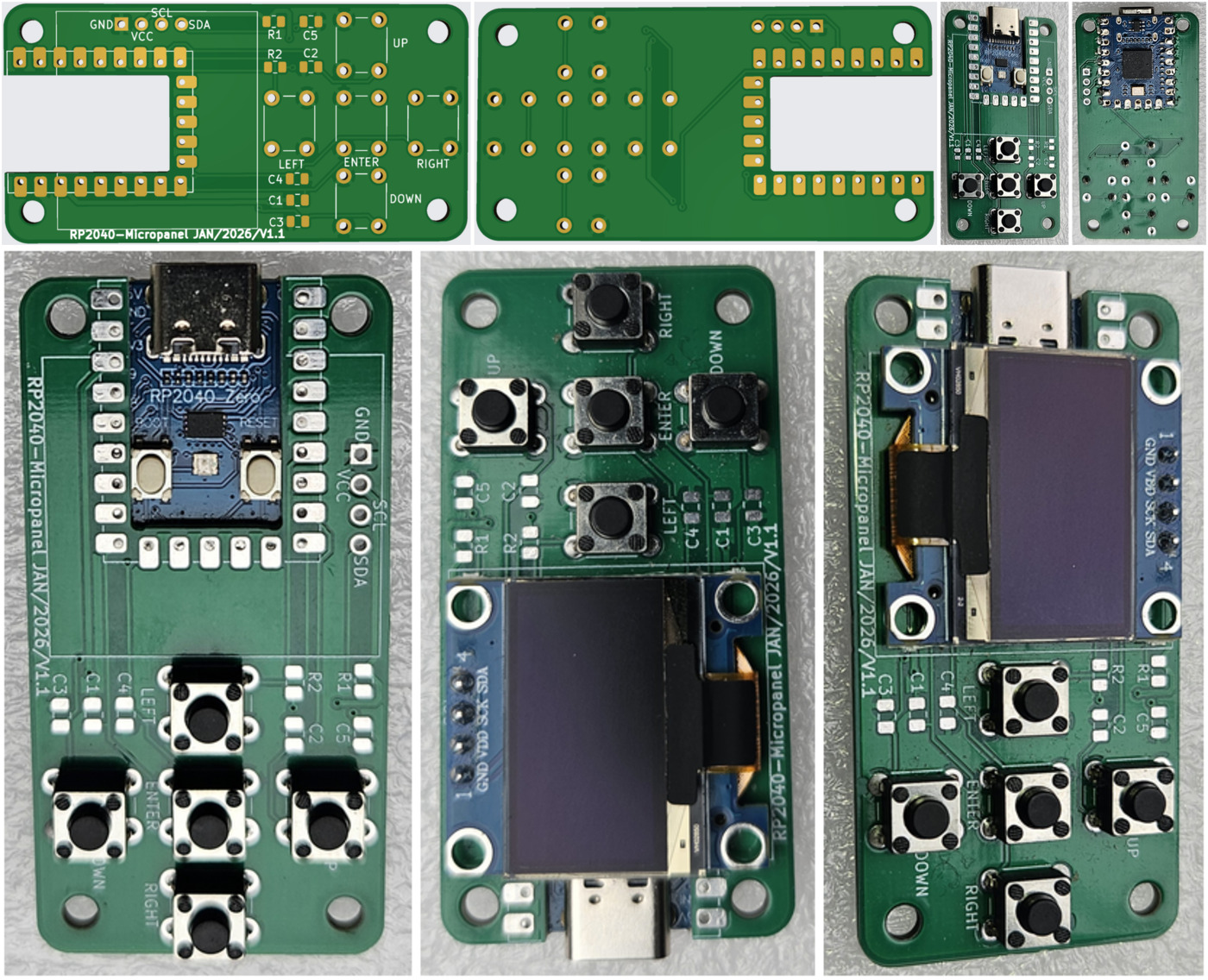
A purpose-built PCB designed in KiCad with a Waveshare RP2040-Zero module, SSD1306 OLED, and 5 tactile buttons on a compact board. KiCad project files are available in the hardware/ directory.
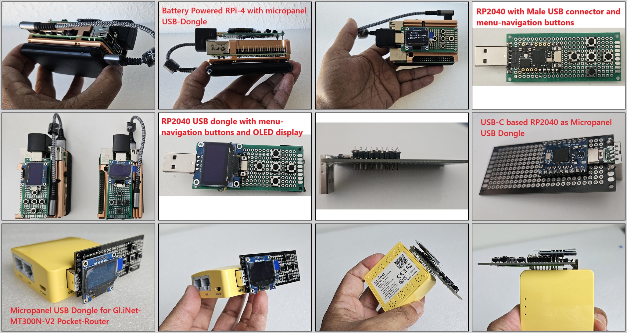
The same firmware runs on any RP2040 board with hand-wired connections on a general-purpose PCB. No custom PCB required — see the wiring diagram in the Directional Push Buttons section below.
| Signal | GPIO | Pico Pin |
|---|---|---|
| SDA | GPIO 4 | Pin 6 |
| SCL | GPIO 5 | Pin 7 |
| VCC | 3.3V | Pin 36 |
| GND | GND | Pin 38 |
| Signal | GPIO | Pico Pin |
|---|---|---|
| CLK (A) | GPIO 10 | Pin 14 |
| DT (B) | GPIO 11 | Pin 15 |
| SW (Button) | GPIO 12 | Pin 16 |
| VCC | 3.3V | Pin 36 |
| GND | GND | Pin 38 |
The firmware detects landscape or portrait mode at boot from GPIO 27:
| GPIO 27 State | Orientation |
|---|---|
| Floating (internal pull-up → HIGH) | Landscape (default) |
| Connected to GND (LOW) | Portrait |
No separate firmware builds needed — a single .uf2 handles both orientations. The detected orientation is reflected in the USB product string ("USB HID Display (landscape)" or "USB HID Display (portrait)").
Pre-compiled .uf2 binary with this GPIO config can be downloaded from here.
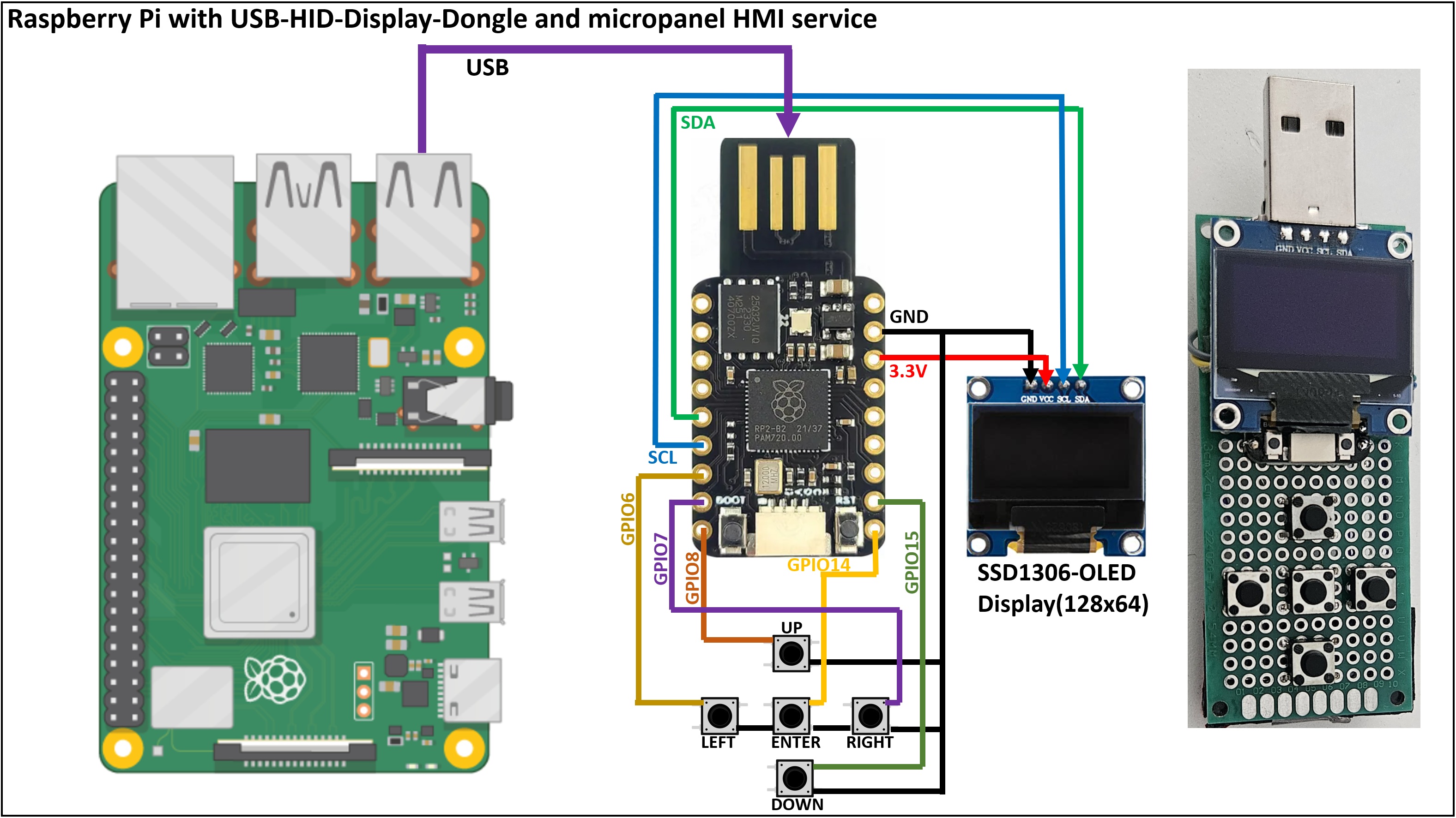
The table below shows the landscape orientation (default) mapping. In portrait mode, the physical button roles rotate: LEFT becomes UP, RIGHT becomes DOWN, DOWN becomes LEFT, UP becomes RIGHT.
| Button (Landscape) | GPIO | HID Action |
|---|---|---|
| LEFT | GPIO 7 | Mouse X = -5 |
| RIGHT | GPIO 6 | Mouse X = +5 |
| UP | GPIO 8 | Mouse Y = -5 |
| DOWN | GPIO 15 | Mouse Y = +5 |
| ENTER | GPIO 14 | Mouse Left Click (shared with rotary SW) |
Portrait/landscape mapping summary:
| Physical Button | Landscape Action | Portrait Action |
|---|---|---|
| LEFT (GPIO 7) | Left | Up |
| RIGHT (GPIO 6) | Right | Down |
| UP (GPIO 8) | Up | Right |
| DOWN (GPIO 15) | Down | Left |
| ENTER (GPIO 14) | Select (BTN_LEFT) | Select (BTN_LEFT) |
Note: Each directional button press generates two HID movement events (one immediate, one after ~16ms) to match rotary encoder step responsiveness. Host-side daemons should account for this when interpreting navigation input.
The device exposes a CDC serial port (/dev/ttyACMx) that accepts binary commands to control the display:
| Command | Code | Format | Description |
|---|---|---|---|
| Clear | 0x01 | [0x01] | Clear entire display |
| Draw Text | 0x02 | [0x02][x][y][len][text...] | Draw len bytes of text at pixel position (x, y). Max len=124. Text Y is 8-pixel aligned (page-based): use multiples of 8 (0, 8, 16, 24, 32, 40, 48, 56) |
| Set Cursor | 0x03 | [0x03][x][y] | Set cursor to pixel position (x, y) |
| Invert | 0x04 | [0x04][0/1] | Normal or inverted display mode |
| Brightness | 0x05 | [0x05][0-255] | Set display contrast/brightness |
| Progress Bar | 0x06 | [0x06][x][y][w][h][0-100] | Draw progress bar at (x, y) with width, height, and percentage |
| Power | 0x07 | [0x07][0/1] | Turn display off or on |
MAX_CMD_SIZE is 128 bytes total per command buffer.CMD_DRAW_TEXT uses length-based framing: the len byte specifies exactly how many text bytes follow (max 124).0, 8, 16, ..., 56.import serial
ser = serial.Serial('/dev/ttyACM0', timeout=1)
# Clear display
ser.write(bytes([0x01]))
# Draw text "Hello" at position (0, 0) — len=5
ser.write(bytes([0x02, 0, 0, 5]) + b'Hello')
# Draw progress bar at (10, 30), 108px wide, 12px tall, 75%
ser.write(bytes([0x06, 10, 30, 108, 12, 75]))
# Set brightness to max
ser.write(bytes([0x05, 255]))When built with -DENABLE_TEST_COMMANDS=ON, the firmware accepts command 0xF0 for automated hardware testing. This allows the host test framework to inject simulated HID input events through the CDC serial port without physically pressing buttons.
Production firmware ignores 0xF0 entirely.
| Subcommand | Code | Action | HID Output |
|---|---|---|---|
| Ping | [0xF0][0x00] | Replies [0xF0][0x00] via CDC | None |
| Rotate CW | [0xF0][0x01] | One clockwise encoder step | REL_X = -5 |
| Rotate CCW | [0xF0][0x02] | One counter-clockwise step | REL_X = +5 |
| Button press | [0xF0][0x03] | Encoder push (press + release) | BTN_LEFT down, then up after ~50ms |
| Navigate up | [0xF0][0x04] | Simulated UP button | 2x REL_Y = -5 (~16ms apart) |
| Navigate down | [0xF0][0x05] | Simulated DOWN button | 2x REL_Y = +5 (~16ms apart) |
| Navigate left | [0xF0][0x06] | Simulated LEFT button | 2x REL_X = -5 (~16ms apart) |
| Navigate right | [0xF0][0x07] | Simulated RIGHT button | 2x REL_X = +5 (~16ms apart) |
Navigation test commands produce orientation-independent logical directions — the same HID output regardless of landscape/portrait build.
Timing: Allow at least 60ms between nav commands and 80ms after button press before sending the next test command. The host test framework can detect test firmware by sending ping and waiting 500ms for a reply.
sudo apt update
sudo apt install git cmake gcc-arm-none-eabi libnewlib-arm-none-eabi build-essential libstdc++-arm-none-eabi-newlibgit clone --recursive https://github.com/raspberrypi/pico-sdk.git ~/pico-sdk
export PICO_SDK_PATH=~/pico-sdk
git clone https://github.com/hackboxguy/usb-hid-display.git
cd usb-hid-display/rp2040/
mkdir build && cd build
cmake .. -DFIRMWARE_VERSION=1.0.0
make -j$(nproc)| Option | Default | Description |
|---|---|---|
FIRMWARE_VERSION | 0.0.0 | Firmware version in X.Y.Z format (each digit 0-9) |
ENABLE_TEST_COMMANDS | OFF | Enable test/debug commands (0xF0) for automated testing |
FIRMWARE_VERSION is embedded in USB descriptors and exposed to the host via sysfs during USB enumeration. Orientation is detected at runtime from the GPIO 27 jumper (no build flag needed).
To build firmware with test commands enabled (for automated hardware testing):
cmake .. -DENABLE_TEST_COMMANDS=ON -DFIRMWARE_VERSION=1.0.1
make -j$(nproc)
Production builds (without -DENABLE_TEST_COMMANDS=ON) ignore the test command byte entirely.
# Check dmesg for the device node (e.g. /dev/sda1)
sudo mount /dev/sdXN /mnt
sudo cp usb_hid_display.uf2 /mnt/
sudo umount /mnt
After flashing, the device enumerates as:
/dev/input/eventX -- HID mouse (rotary encoder + buttons)/dev/ttyACMX -- CDC serial port (display commands)# Test HID input events
sudo evtest /dev/input/eventX
# Test display commands
echo -ne '\x01' > /dev/ttyACM0 # clear display
echo -ne '\x02\x00\x00\x05Hello' > /dev/ttyACM0 # draw "Hello" at (0,0), len=5| Field | Value |
|---|---|
| Vendor ID | 0x1209 (pid.codes) |
| Product ID | 0x0001 |
| Manufacturer | hackboxguy |
| Product | USB HID Display (<orientation>) — reflects runtime GPIO jumper state |
| Serial | Unique per chip (from RP2040 flash ID) |
| bcdDevice | Firmware version as BCD (e.g. 0x1010 for v1.0.1) |
FIRMWARE_VERSION=X.Y.Z is encoded as USB bcdDevice = 0xXYZ0:
| Version | bcdDevice |
|---|---|
1.0.0 | 1000 |
1.0.1 | 1010 |
1.1.0 | 1100 |
The daemon (or any tool) can read firmware version and orientation from sysfs without opening the serial port:
# Find the device (filter by VID:PID)
DEVPATH=$(grep -rl "1209" /sys/bus/usb/devices/*/idVendor 2>/dev/null | head -1 | xargs dirname)

# Read product string (includes orientation)
cat "$DEVPATH/product"    # e.g. "USB HID Display (portrait)"

# Read firmware version (BCD format)
cat "$DEVPATH/bcdDevice" # e.g. "1100" for v1.1.0Use stable paths instead of raw eventX / ttyACM0 indices:
# serial path
ls -l /dev/serial/by-id/

# input path
ls -l /dev/input/by-id/
Optional udev rule for a stable symlink:
# /etc/udev/rules.d/99-usb-hid-display.rules
SUBSYSTEM=="tty", ATTRS{idVendor}=="1209", ATTRS{idProduct}=="0001", SYMLINK+="usb-hid-display-%s{serial}"sudo udevadm control --reload-rules
sudo udevadm trigger| Symptom | Likely Cause | Check / Fix |
|---|---|---|
No /dev/ttyACM* | USB cable or enumeration issue | Try a data-capable cable, check dmesg -w |
| No HID events | Wrong eventX selected | Use evtest and pick matching device from /dev/input/by-id |
| Display stays blank | I2C wiring/power/address issue | Verify SDA/SCL pins, 3.3V power, GND, SSD1306 address 0x3C |
| Buttons feel double-step | Intended dual-event behavior | Account for two events per press in daemon logic |
| Wrong navigation direction | Orientation mismatch | Check GPIO 27 jumper: GND = portrait, floating = landscape |
| Permission denied on device files | User/group access | Add user to dialout and input groups or use udev permissions |
See LICENSE for details.
| Qty | Value | Footprint | References |
|---|---|---|---|
| 5 | 0.1uF/50V | Ezra_Parts:C_0805_2012Metric | C1, C2, C3, C4, C5 |
| 4 | MountingHole_2.7mm_M2.5 | MountingHole:MountingHole_2.7mm_M2.5 | MH1, MH2, MH3, MH4 |
| 2 | 4.7K/1% | Ezra_Parts:R_0805_2012Metric | R1, R2 |
| 2 | SSD1306 | adav-footprints:ssd1306-module | U1, U2 |
| 1 | DOWN | Button_Switch_THT:SW_PUSH_6mm | SW2 |
| 1 | ENTER | Button_Switch_THT:SW_PUSH_6mm | SW5 |
| 1 | LEFT | Button_Switch_THT:SW_PUSH_6mm | SW3 |
| 1 | Portrait-Mode | Jumper:SolderJumper-2_P1.3mm_Open_TrianglePad1.0x1.5mm | JP1 |
| 1 | RIGHT | Button_Switch_THT:SW_PUSH_6mm | SW4 |
| 1 | RP2040-Zero | adav-footprints:RP2040-Zero | RZ1 |
| 1 | UP | Button_Switch_THT:SW_PUSH_6mm | SW1 |
It measures 59.3 × 30.5 mm and has 2 copper layers, 1.6 mm thick.
20 parts, built around the 0.1UF 50V 5*11 and RP2040-ZERO. The full list of its parts is on this page, with links to each part's symbol and footprint where PCBKit's library has them.
From the hackboxguy/usb-hid-display repository on GitHub, at the commit this page was made from: the board is hardware/usb-hid-display.kicad_pcb and its schematic hardware/usb-hid-display.kicad_sch. PCBKit opens the board in the browser, with nothing to install.
Its repository publishes it under the GPL-3.0 licence: you may reuse it on that licence's terms (keep the author's notice, and for a copyleft licence share your changes alike).
EnriqueNeyra/Aeroq
An Indoor Air Quality Monitor Powered by ESP32, SCD40, and SEN54

EnriqueNeyra/aether
All-in-one home air quality monitor measuring Temp, Humidity, CO2, VOCs, Particulate Matter, and NOx. Powered by ESP32-C3 running esphome, and built with Home Assistant integration


CuriousMotor/Onyx-Stepper-Motherboard
The successor of the iconic Arduino-CNC-shield


db-electronics/triple-bypass-kicad
An audio and video bypass circuit for the Sega Genesis

