
6 layers85 × 56 mm
Karnix ASB
Fabmicro-LLC/Karnix_ASB-254
Karnaugh Interactive Extendable ASIC Simulation Board AKA Karnix ASB-254
368 parts19

 ha7dcd/QRPi_WSPR_PCB6
QRPi PCB for 20
20m QRPi 1V6 is an open-source printed circuit board by ha7dcd, from the ha7dcd/QRPi_WSPR_PCB repository on GitHub. It is a 2-layer board of 45.3 × 24.5 mm with 33 parts on 24 nets, routed with 98 tracks and 144 vias.
It is built around the PGB1010603NRHF. Its parts include 12 capacitors, 7 inductors, 2 resistors, 1 transistor and 1 connector.
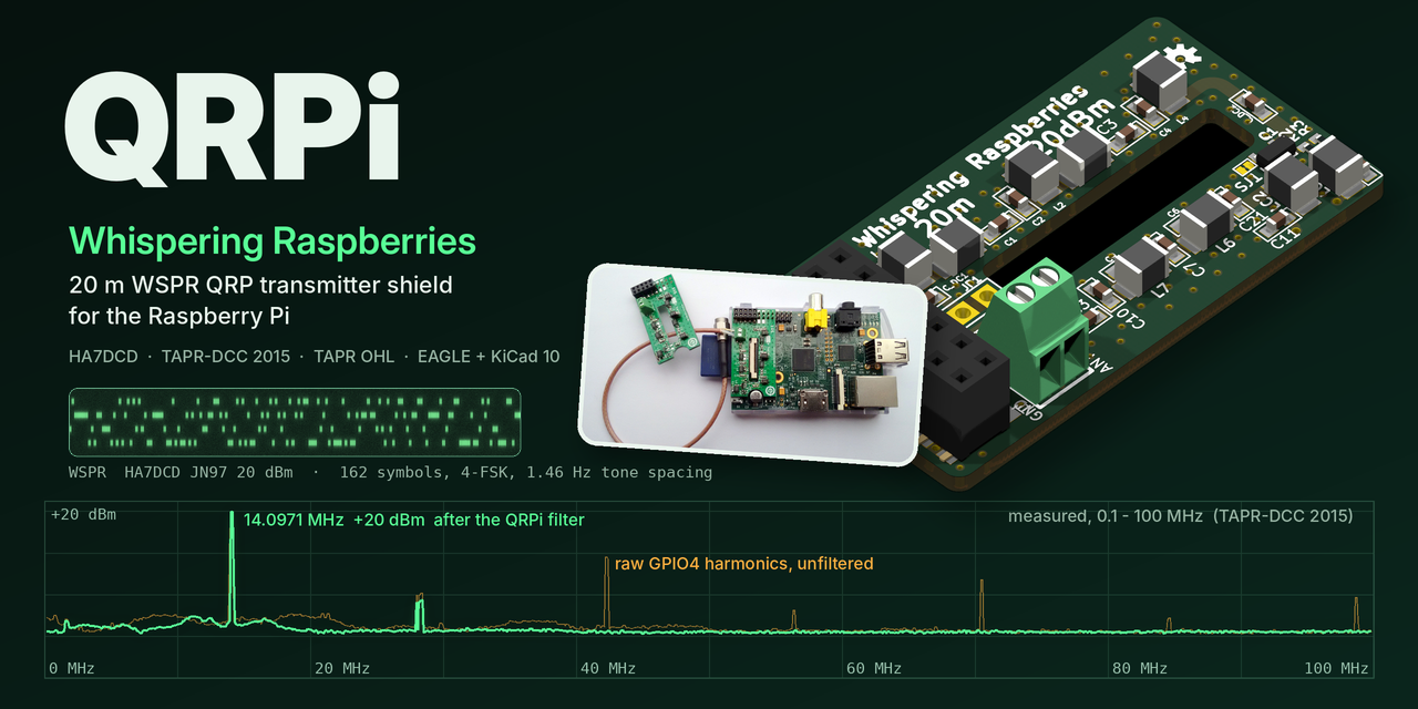
QRPi is a 20 m band, 20 dBm RF signal conditioner shield for the Raspberry Pi. It takes the RF square wave that the Pi generates on a GPIO pin and turns it into a clean, filtered QRP transmit signal: a MOSFET (MMBF170) stage followed by a multi-section low-pass filter. It was presented as a TAPR-DCC 2015 talk paper and was sold through TAPR and on Amazon.
This repository holds the board's original EAGLE design and manufacturing files (rev 1.6), and a KiCad 10 version of the same design.
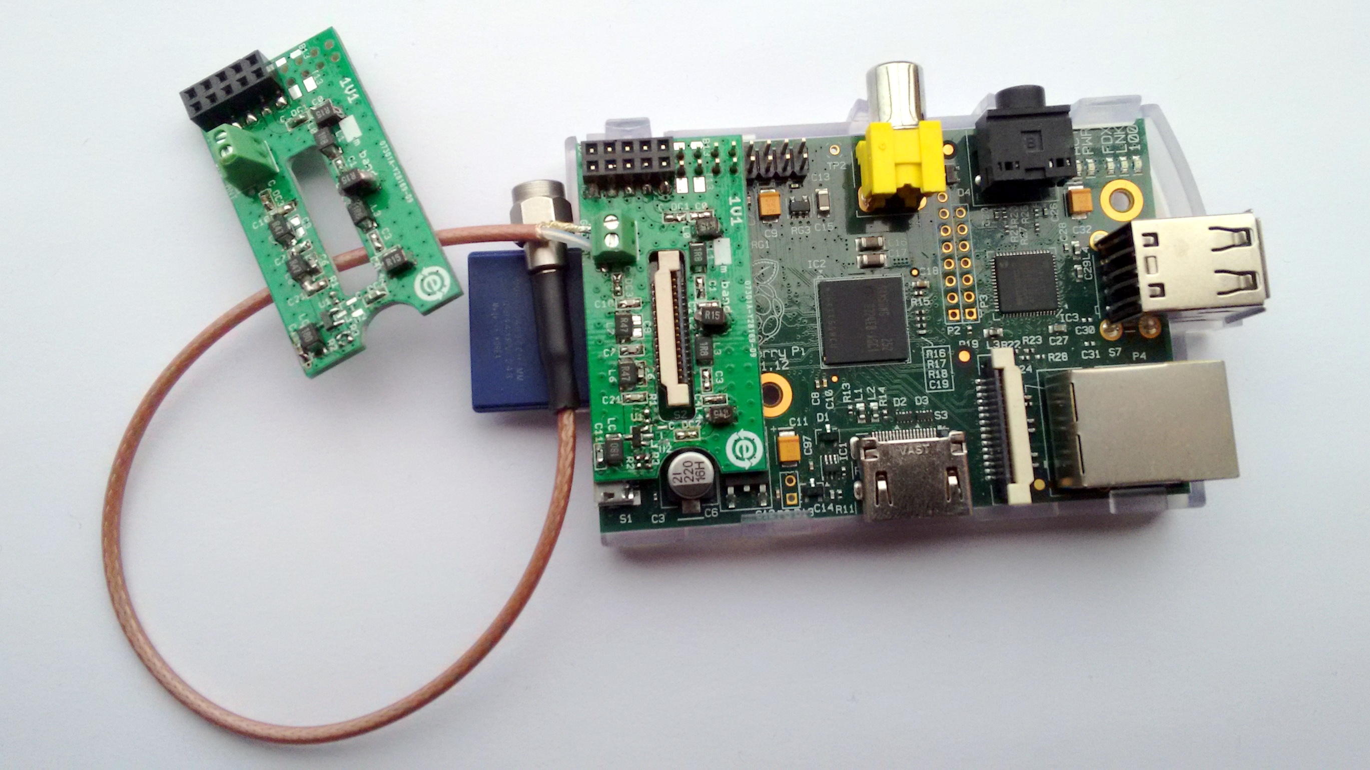
An earlier prototype (rev 1.1) on a Raspberry Pi model B, with a coax pigtail on the antenna terminal.
QRPi - A Raspberry Pi QRP TX Shield Design, TAPR-DCC Talk paper 2015 (PDF in this repo)
QRPi is an RF signal conditioner shield for Raspberry Pi. Sourcing the RaspberryPi generated RF signal from GPIO4.
Right now existing only for the 20m band for 14.0971 MHz Later on will designed for other bands as well (10m in prototype).
In default GPIO4 mode can be used with WsprryPi, SSTV, CW, check manual here: j.mp/tapr-qrpi GPIO4 mode works with RPi 1 B, B+ and RPi 2 as well for WSPR mode. When using in the experimental GPIO18 mode (solder jumper selectable; SSB USB, LSB, NFM, WFM, AM with qtcsdr and rpitx) it works only with RPi 2 right now (due to CPU demand)
However please be aware that QRPi was engineered and tested for GPIO4 pin, using WSPR modulation! I'm adding GPIO18 option for experimental mode only to use with qtcsdr and rpitx! By default the solder jumper is set for GPIO4 by short cut. As for VFO operation (CW signal) GPIO18 works nice but not yet tested comprehensively for other modulation yet, please take care of this in shake of RF spectrum emission! The QRPi shield is available at TAPR's webshop: https://www.tapr.org/kits_20M-wspr-pi.html
Now available at Amazon too: https://www.amazon.com/Raspberry-QRP-Sheild-WSPR-Meters/dp/B01FWFKN40/
Thanks for your interest!
73, HA7DCD
Video: https://www.youtube.com/watch?v=w-OTpw2Ai0k
| Top | Bottom |
|---|---|
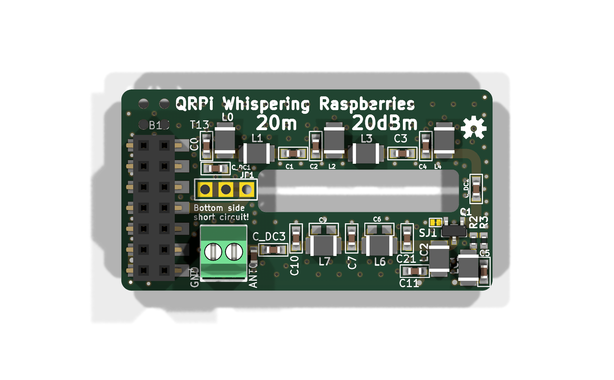 | 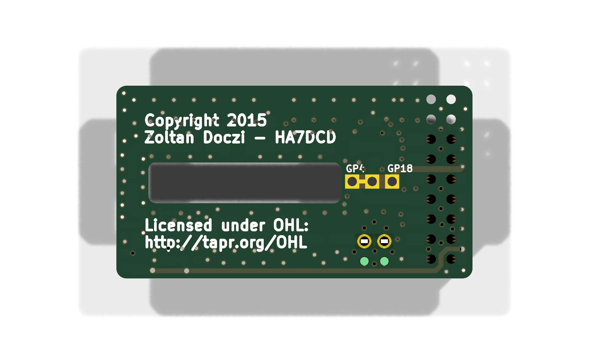 |
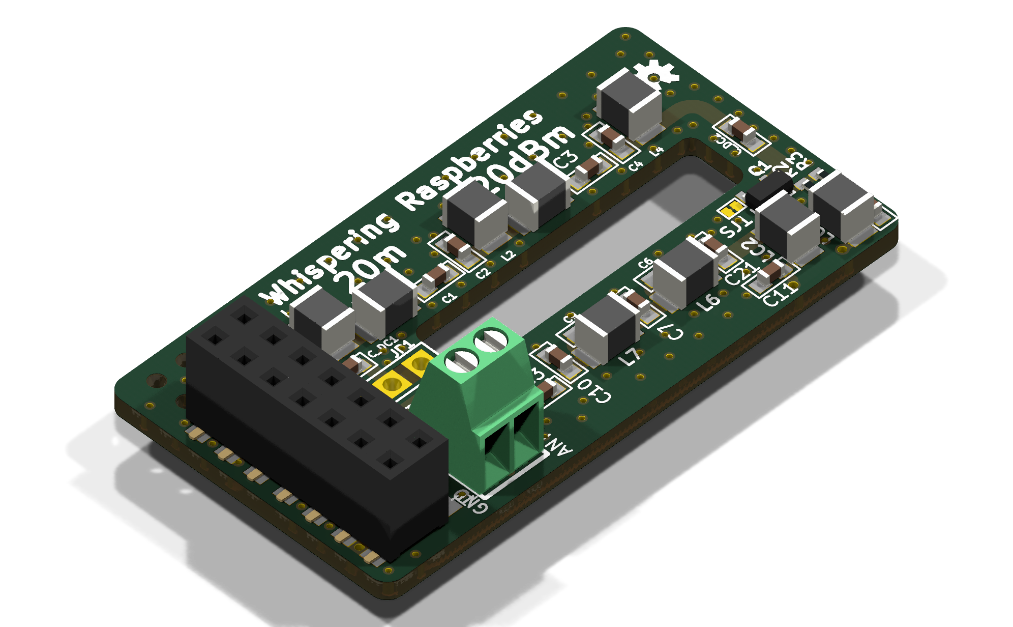
Two-layer board. The Raspberry Pi GPIO header pins pass through the board and into a 2x7 SMD female socket on the top side. The antenna is connected to a 2-pole Phoenix MPT 0,5/2-2,54 screw terminal. The GPIO4 / GPIO18 drive is selected on the bottom side: GPIO4 is shorted by default.
| Path | What it is |
|---|---|
Eagle/20m_QRPi_1V6.sch, Eagle/20m_QRPi_1V6.brd | Original EAGLE schematic and board (EAGLE 6.4 XML format) |
Eagle/20m_QRPi_1V6_sch.pdf, _top.pdf, _bot.pdf | Schematic and board prints |
Eagle/20m_RPI_WSPR_TX_BOM_SMDmount.xlsx | Bill of materials (SMD assembly) |
Eagle/CAM/20m_RPI_WSPR_TX_1v6.zip | Original manufacturing files: Gerbers, Excellon drill files, PDFs |
KiCad/ | KiCad 10 project: schematic, PCB, project symbol and footprint libraries, design rules |
KiCad/3dmodels/ | STEP models used by the 3D view, from the KiCad standard library |
docs/ | TAPR-DCC 2015 paper, prototype photo, 3D renders, banner |
The KiCad project was converted from the EAGLE files with Eagle Exhumer and then checked against the EAGLE source and the original manufacturing files:
Only the EAGLE drawing frame was removed (KiCad draws its own page frame). 3D models were added for 30 of 33 footprints; the solder jumpers JP1 and SJ1 and the OSHW logo have none.
Copyright 2015 Zoltan Doczi - HA7DCD. The hardware design is licensed under the TAPR Open Hardware License (http://tapr.org/OHL).
The STEP models in KiCad/3dmodels/ come from the KiCad library (CC-BY-SA 4.0 with an exception that allows their use in designs, see https://www.kicad.org/libraries/license/).
| Qty | Value | Footprint | References |
|---|---|---|---|
| 3 | 220nF | 20m_QRPi_1V6-import-fps:0603 | C_DC1, C_DC2, C_DC3 |
| 2 | 0.27uH | 20m_QRPi_1V6-import-fps:L1210 | L0, L4 |
| 2 | 0.56uH | 20m_QRPi_1V6-import-fps:L1210 | L6, L7 |
| 2 | 10nF | 20m_QRPi_1V6-import-fps:0603 | C5, C11 |
| 2 | 2.7uH | 20m_QRPi_1V6-import-fps:L1210 | L1, L3 |
| 2 | 330p | 20m_QRPi_1V6-import-fps:0603 | C10, C21 |
| 2 | 390p | 20m_QRPi_1V6-import-fps:0603 | C0, C4 |
| 2 | 39p | 20m_QRPi_1V6-import-fps:0603 | C1, C3 |
| 2 | 47uH | 20m_QRPi_1V6-import-fps:L1210 | LC1, LC2 |
| 2 | N.F. | 20m_QRPi_1V6-import-fps:0603 | C6, C9 |
| 1 | 0.18uH | 20m_QRPi_1V6-import-fps:L1210 | L2 |
| 1 | 1.2k | 20m_QRPi_1V6-import-fps:R0402 | R2 |
| 1 | 1k | 20m_QRPi_1V6-import-fps:R0402 | R3 |
| 1 | 470p | 20m_QRPi_1V6-import-fps:0603 | C2 |
| 1 | 680p | 20m_QRPi_1V6-import-fps:0603 | C7 |
| 1 | JUMPER_SMD_MICRO_SHORT | 20m_QRPi_1V6-import-fps:JUMPER_SMD_MICRO_SHORT | SJ1 |
| 1 | MMBF170-7-F | 20m_QRPi_1V6-import-fps:SOT103P240X110-3N | Q1 |
| 1 | N.F. | 20m_QRPi_1V6-import-fps:PIN3-B_SHORT23 | JP1 |
| 1 | OSHW-LOGOS | 20m_QRPi_1V6-import-fps:OSHW-LOGO-S | U$15 |
| 1 | PGB1010603NRHF | 20m_QRPi_1V6-import-fps:0603__v2 | ESD1 |
| 1 | TERMINAL_WIRE_2P_17256562P | 20m_QRPi_1V6-import-fps:WIRE_CONTACT_2P | ANT0 |
| 1 | smd header | 20m_QRPi_1V6-import-fps:2X7-SMT_CROSSPCB_ASSYM_DUMY26HOLES | CON1 |
Fabmicro-LLC/Karnix_ASB-254
Karnaugh Interactive Extendable ASIC Simulation Board AKA Karnix ASB-254

hoglet67/RGBtoHDMI
Bare-metal Raspberry Pi project that provides pixel-perfect sampling of Retro Computer RGB/YUV video and conversion to HDMI

mntmn/amiga2000-gfxcard
MNT VA2000, an Open Source Amiga 2/3/4000 Graphics Card (Zorro II/III), written in Verilog

hackclub/OnBoard
💡 Join 1,000 teenagers and make your first PCB with a $100 grant!

Arrow-air/project-quiver
Project Quiver documentation, designs, and project artifacts.

ozel/DIY_particle_detector
A mobile low-cost spectrometer for measuring radioactivity and the energy of ionising radiation like alpha particles and electrons

BlueAndi/Pixelix
Full RGB LED matrix, based on an ESP32 and WS2812B LEDs or emulated LEDs on TFT.

jrsteensen/OpenHornet
OpenHornet 1:1 F/A-18C Simulator Repository
It measures 45.3 × 24.5 mm and has 2 copper layers, 1.6 mm thick.
33 parts, built around the PGB1010603NRHF. The full list of its parts is on this page, with links to each part's symbol and footprint where PCBKit's library has them.
From the ha7dcd/QRPi_WSPR_PCB repository on GitHub, at the commit this page was made from: the board is KiCad/20m_QRPi_1V6.kicad_pcb and its schematic KiCad/20m_QRPi_1V6.kicad_sch. PCBKit opens the board in the browser, with nothing to install.
Its repository states no licence, so its author keeps all rights: ask ha7dcd before reusing the design.