

2 layers37 × 19 mm
Passive rpi hub75-adapter
hzeller/rpi-rgb-led-matrix
Controlling up to three chains of 64x64, 32x32, 16x32 or similar RGB LED displays using Raspberry Pi GPIO
2 parts4.4kGPL-2.0
 gzalo/ncomputing-l13012
Ncomputing L130 PCB reverse engineering
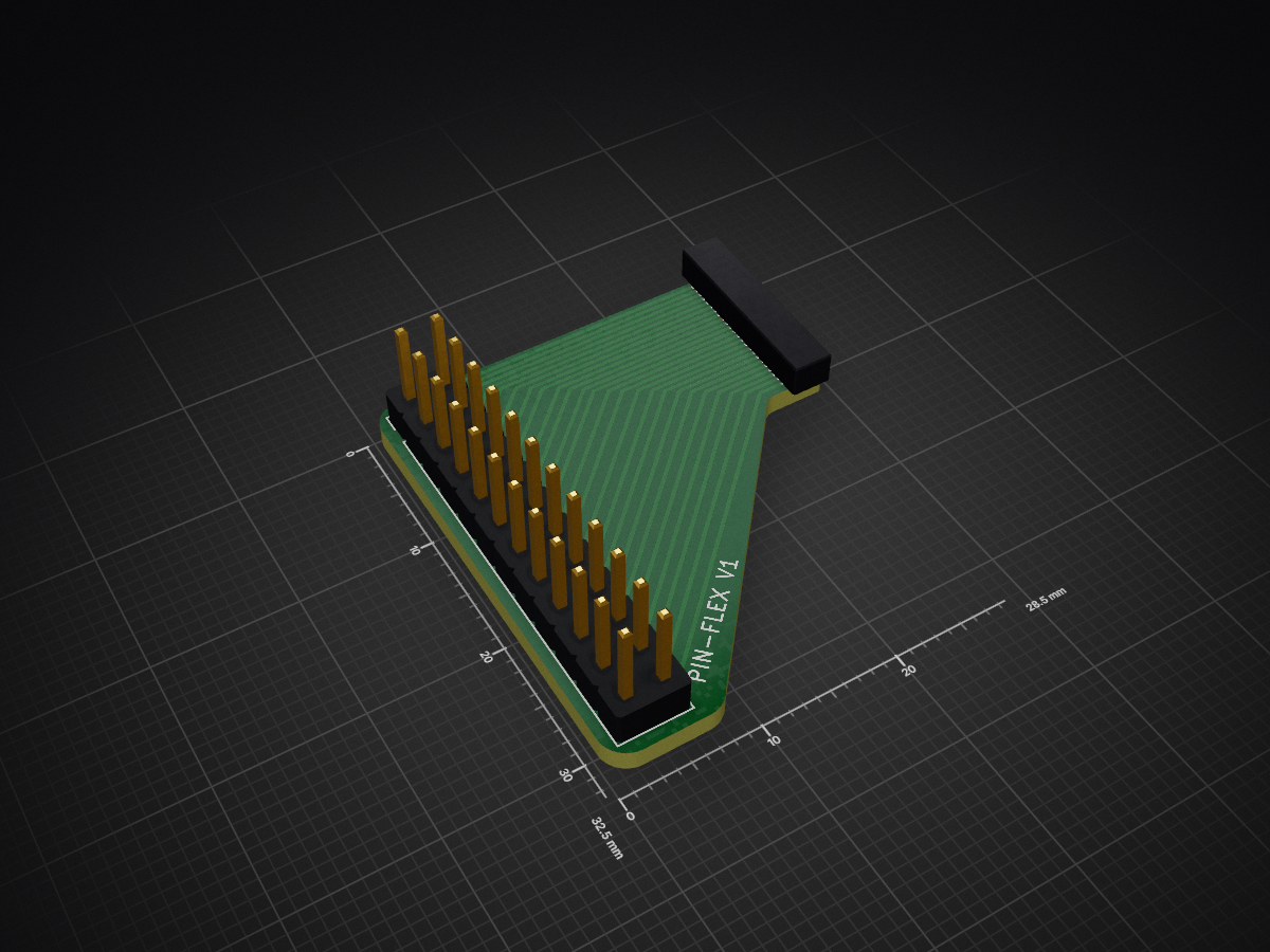
Pin flex is an open-source printed circuit board by gzalo, from the gzalo/ncomputing-l130 repository on GitHub, published under the MIT licence. It is a 2-layer board of 28.5 × 32.5 mm with 2 parts on 24 nets, routed with 85 tracks and 0 vias.
The idea of this project is to reverse engineer the Ncomputing L130 PCB (rev 1.3A), to be able to use it as a generic FPGA development board.
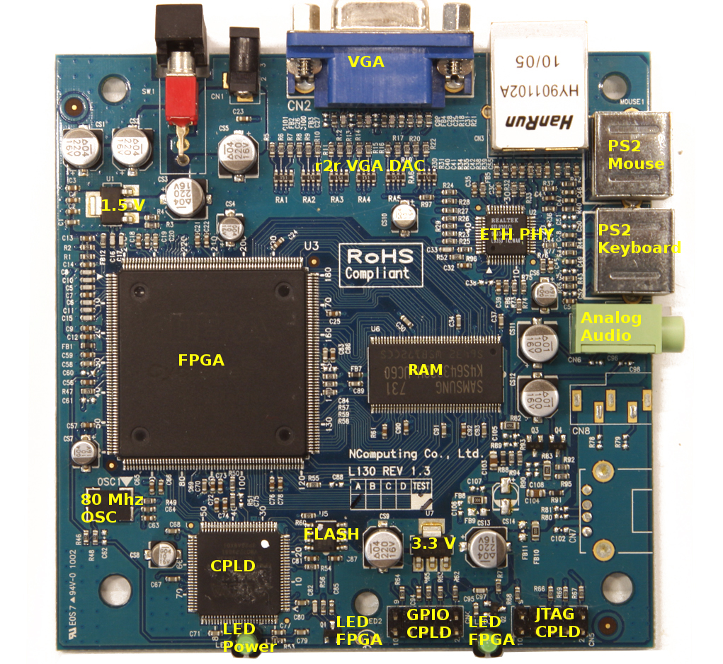
Status:
KiCad files can be found in the pcb/ folder.
Full component list here (may be missing some values, or have errors)
PCB Top layer / PCB Bottom layer
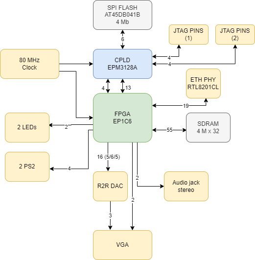
The following folders contain vhd files that can be used to create a Quartus II project for this board:
Getting started: guide to building the projects and programming the board
Newer Windows note: USB Blaster clones no longer work reliably due to driver issues. Using a Windows XP virtual machine with USB passthrough is a better option for programming.
In the pin-flex folder you can find files to manufacture a very simple flexible PCB that is useful to map out certain unused pins:
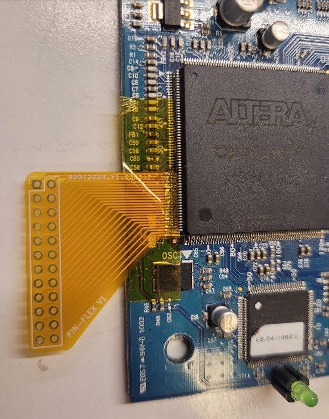
To use it, you need to remove R47 and C61, and lift the existing pins using a needle or something similar, while keeping pin 40, 51 and 52 connected to the original board.
The docs folder contains many documents that are useful for this project.
When using Quartus to generate the bitstream, remember that by default non defined pins are marked as outputs and are LOW. This can cause short circuits and destroy the rest of the circuit. To avoid that, you should go to Assignments->Device->Device and Pin Options...->Unused Pins and set it to "As input tri-stated with weak pull-up". DO THIS FOR BOTH PROJECTS!
| Qty | Value | Footprint | References |
|---|---|---|---|
| 1 | Conn_01x24 | pin-con-lib:24-pin-0.5 | J1 |
| 1 | Conn_02x12_Odd_Even | Connector_PinHeader_2.54mm:PinHeader_2x12_P2.54mm_Vertical | J2 |
It measures 28.5 × 32.5 mm and has 2 copper layers, 1.6 mm thick.
2 parts. The full list of its parts is on this page, with links to each part's symbol and footprint where PCBKit's library has them.
From the gzalo/ncomputing-l130 repository on GitHub, at the commit this page was made from: the board is pin-flex/pin-flex.kicad_pcb and its schematic pcb/l130.kicad_sch. PCBKit opens the board in the browser, with nothing to install.
Its repository publishes it under the MIT licence: you may reuse it on that licence's terms (keep the author's notice, and for a copyleft licence share your changes alike).
hzeller/rpi-rgb-led-matrix
Controlling up to three chains of 64x64, 32x32, 16x32 or similar RGB LED displays using Raspberry Pi GPIO


adamws/kicad-kbplacer
KiCad plugin for automatic keyboard's key placement and routing

Luos-io/luos_engine
Open-source and real-time orchestrator for cyber-physical-systems, to easily design, test and deploy embedded applications and digital twins.

NVNTLabs/switch2-SDEX2M2
Micro SD Express to M.2 NVME Adapter for Nintendo Switch 2

BlueSCSI/BlueSCSI-v2
BlueSCSI v2/Ultra - an open source, open hardware, SCSI emulator using the Pi Pico PR2040 and Pico 2 RP2350

ohmtech-rdi/eurorack-blocks
Software to Hardware Prototyping for Eurorack using C++, Max/Gen~ or Faust
