4 layers189.9 × 136.5 mm
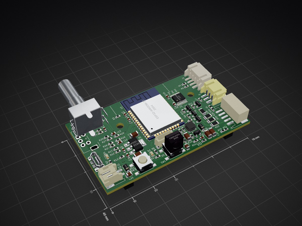
 Gustice/LightController3
A ESP32 based LED-Controller for various light scenarios
Controller is an open-source printed circuit board by Gustice, from the Gustice/LightController repository on GitHub, published under the MIT licence. It is a 4-layer board of 70 × 40 mm with 108 parts on 78 nets, routed with 947 tracks and 175 vias.
It is built around the ESP32-WROOM-32, LMR62421XMF and 74AXP4T245BQX, with the SS24FL among its other parts. Its parts include 52 resistors, 22 capacitors, 13 connectors, 6 diodes and 5 ICs. It belongs with the ESP32 boards of this library.


A ESP32 based LED-Controller for various light scenarios.
This project is intended to be used as base platform for various Light projects. Its based on the ESP32 WiFi SoC and utilizes the Espressif development framework (ESP-IDF).
On top of that this is a small hardware and board abstraction layer that simplifies the hardware access and provides further bases for device implementation.
The main purpose is of course to have fun an learn several new techniques and hacks. I also hoped to dig into a promising WiFi platform that enables a wide band of applications. As I happily discovered it was absolutely worth the time and I'm glad that I didn't stuck to arduino.
The intended Products that should result from this are extreme fancy night lights for bedrooms of my children and the stairwell and low key disco lights / ambient lights for the living room.
This platform is capable of driving most LEDs I encountered so far (at least the very most common LEDs I have seen so far).
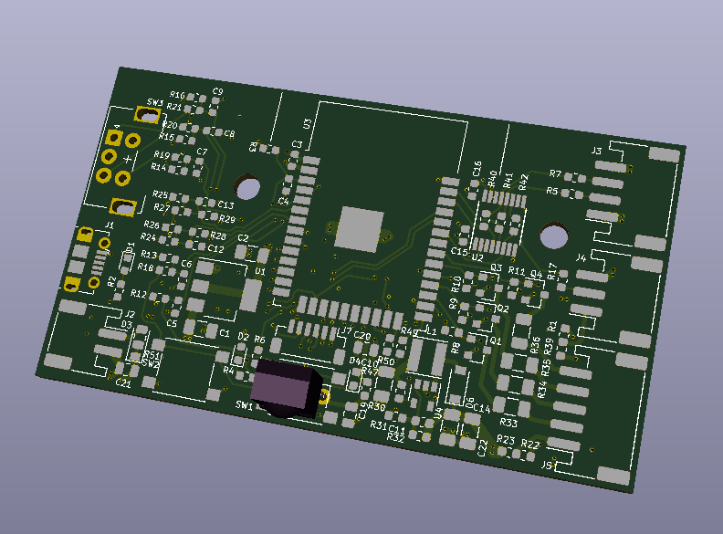
The main board integrates two switches, two analogue inputs and 1 encoder to be integrated in controlling of the station. It also can utilize a UART interface to other protocol bridges or a infrared interface which are also both prepared (the IR-Interface would come at cost of one digital function).
The board also aims to drive short LED-strips solidly with 5 V power supply. Hence it integrates also a small boost-converter.
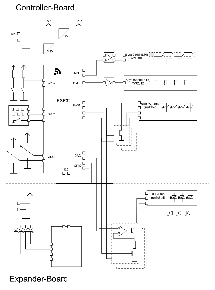
The next picture shows a block diagram of the platform. Note that the expander board is not designed yet and the main-board will be eventually redesigned to be smaller an perhaps also provide a battery management circuitry.
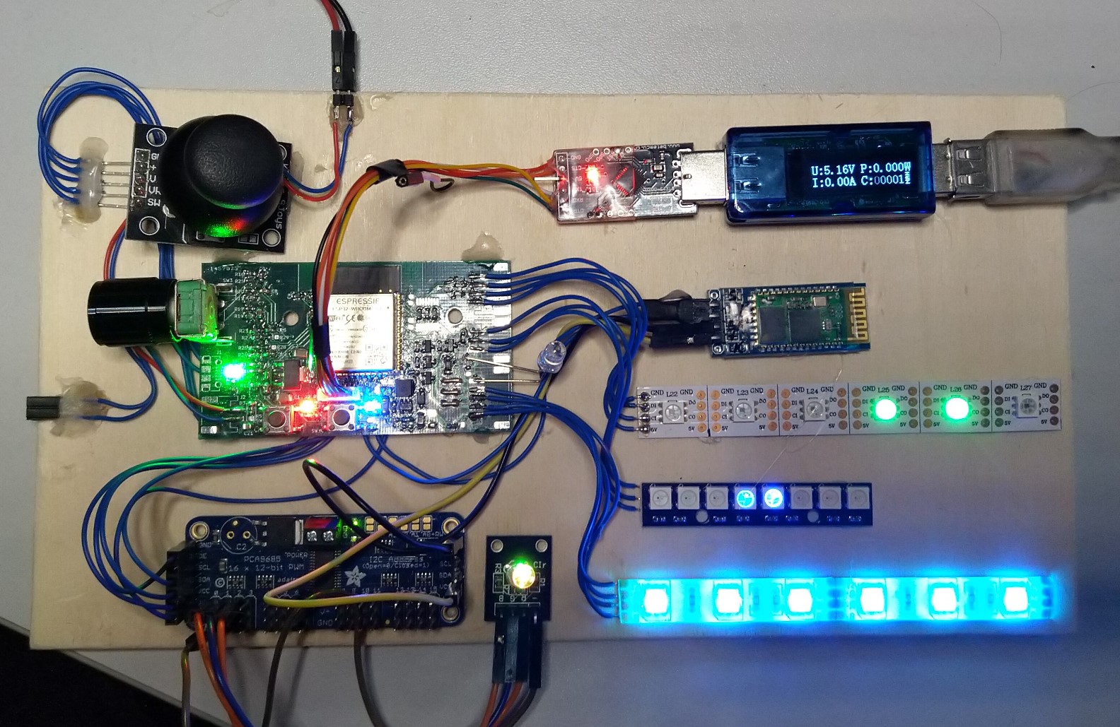
The next picture shows the first Device I build up. It is solidly for implementation purpose.
The next picture shows a web GUI page to control the LED colors. It currently only supports to control exactly the first LED of each channel.
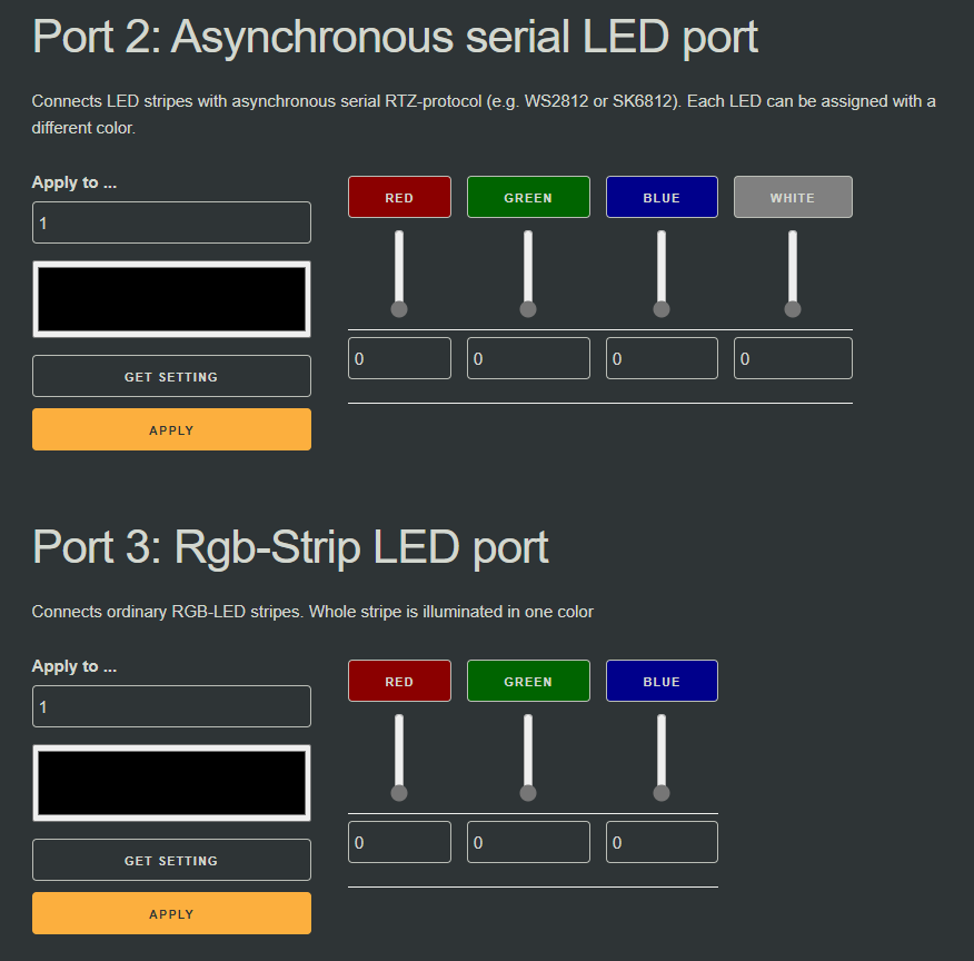
There is currently not very much useful stuff going on. But to get faster familiar with this project this could help you to read.
The device is flashed in three steps. One can use the VS-Tasks defined in the Firmware-Project for it:
Flash & Monitor: Builds and flashes the app to target. Note that certain config files will be remain missing until also the parameter partition and webserver partition is also flashed.Flash Data-Image: Flashes the config files on the parameter partition (therefor the folder factoryCfg is packed to binary and flashed)Flash Web-Image: Flashes the files for the webserver to the server partition (therefor the folder serverPages is backed to binary and flashed)After powerup the device provides a WiFi-access point.
cLightFiatLux!You can connect to the device and display the root page by typing e.g. "192.168.4.1/" (at least in my case). On this page you see some (currently) little relevant in formation and can navigate to set up your WiFi-parameter or to setup the Lights.
The development is done in Visual Studio Code so far. To be able to join the development you must have the IDF installed. Add also the path to the installed IDF as system path variable.
Note: This project is based on the idf version ESP-IDF v4.2-dev-1034-ge599b794b. I missed the step to stick to a certain tag or something. Sorry for that. You pretty sure will have to make minor adaptions on things like Queues or Wifi parameter.
However, to be able to compile the code you must start vs code from command line with exported environment variables
%IDF_PATH%\export.bat to setup the environment for used toolchaincode . to open current path in VS CodeCtrl+Shift+BTo be able to flash your ESP you need a USB to UART bridge, that also exposes RTS and DTR pins. These are needed to reset and set the ESP32 into programming mode.
Note: Many of the components are partly ore even mostly tested by unit-tests (that are run locally on the computer not on the SoC). Currently catch2 is used as test-framework.
Note: You can also use the ServerMock.py script to emulate parts of the behavior of the http-webserver. At least display and the navigation across the websites. Also partly demo data is already generated.
This project is anything but finished. I have several open tasks and they somehow appear to increase rather than getting less.
| Qty | Value | Footprint | References |
|---|---|---|---|
| 19 | 10k | Resistor_SMD:R_0603_1608Metric | R3, R10, R11, R12, R13, R14, R15, R16, R28, R29, R30, R31, R37, R38, R48, R49 +3 |
| 12 | 100nF | Capacitor_SMD:C_0603_1608Metric | C3, C4, C5, C6, C7, C8, C9, C12, C13, C15, C16, C18 |
| 11 | 100R | Resistor_SMD:R_0603_1608Metric | R18, R19, R20, R21, R26, R27, R43, R44, R45, R46, R47 |
| 7 | 0R | Resistor_SMD:R_0603_1608Metric | R1, R5, R7, R17, R22, R23, R39 |
| 5 | NC | Resistor_SMD:R_0603_1608Metric | R24, R25, R40, R41, R42 |
| 4 | 0R | Resistor_SMD:R_1206_3216Metric | R33, R34, R35, R36 |
| 4 | 1uF | Capacitor_SMD:C_0805_2012Metric | C17, C19, C20, C21 |
| 4 | IRLML2030 | Package_TO_SOT_SMD:SOT-23 | Q1, Q2, Q3, Q4 |
| 3 | 10uF | Capacitor_SMD:C_1206_3216Metric | C1, C2, C10 |
| 3 | SS24FL | Diode_SMD:D_SOD-123 | D3, D5, D6 |
| 2 | 2x4 2mm | Connector_PinSocket_2.00mm:PinSocket_2x04_P2.00mm_Vertical_SMD | J11, J12 |
| 2 | 4,7uF | Capacitor_SMD:C_1206_3216Metric | C14, C22 |
| 2 | 470R | Resistor_SMD:R_0603_1608Metric | R4, R6 |
| 2 | NC | Resistor_SMD:R_0805_2012Metric | R51, R52 |
| 2 | PH-S3B | Connector_JST:JST_PH_S3B-PH-SM4-TB_1x03-1MP_P2.00mm_Horizontal | J4, J8 |
| 2 | PH-S4B | Connector_JST:JST_PH_S4B-PH-SM4-TB_1x04-1MP_P2.00mm_Horizontal | J3, J9 |
| 2 | PH-S5B | Connector_JST:JST_PH_S5B-PH-SM4-TB_1x05-1MP_P2.00mm_Horizontal | J5, J6 |
| 2 | SW_SPST | Button_Switch_SMD:SW_Push_1P1T_NO_6x6mm_H9.5mm | SW1, SW2 |
| 1 | 10 uH | Inductor_SMD:L_Taiyo-Yuden_MD-4040 | L1 |
| 1 | 2.2k | Resistor_SMD:R_0603_1608Metric | R2 |
| 1 | 56pF | Capacitor_SMD:C_0603_1608Metric | C11 |
| 1 | 74AXP4T245 | Package_SO:TSSOP-16_4.4x5mm_P0.65mm | U2 |
| 1 | 86k | Resistor_SMD:R_0603_1608Metric | R32 |
| 1 | AP1117-33 | Package_TO_SOT_SMD:SOT-223-3_TabPin2 | U1 |
| 1 | EN12-VS11AF18 | _ProjectParts:RotaryEncoder_EN12-VS11AF18 | SW3 |
| 1 | ESP32-WROOM-32 | RF_Module:ESP32-WROOM-32 | U3 |
| 1 | LMR62421XMF | Package_TO_SOT_SMD:SOT-23-5 | U4 |
| 1 | Micro_SD_Card_Det | Connector_Card:microSD_HC_Molex_104031-0811 | J13 |
| 1 | PH-S2B | Connector_JST:JST_PH_S2B-PH-SM4-TB_1x02-1MP_P2.00mm_Horizontal | J2 |
| 1 | PH-S6B | Connector_JST:JST_PH_B6B-PH-SM4-TB_1x06-1MP_P2.00mm_Vertical | J10 |
| 1 | SH-BM6 | Connector_JST:JST_SH_BM06B-SRSS-TB_1x06-1MP_P1.00mm_Vertical | J7 |
| 1 | TSDP341xx | OptoDevice:Vishay_MOLD-3Pin | U5 |
| 1 | USB_B_Micro | Connector_USB:USB_Micro-B_Molex-105017-0001 | J1 |
| 1 | blue | LED_SMD:LED_0603_1608Metric | D4 |
| 1 | green | LED_SMD:LED_0603_1608Metric | D1 |
| 1 | red | LED_SMD:LED_0603_1608Metric | D2 |
The 106 most common of 108 parts.
It measures 70 × 40 mm and has 4 copper layers, 1.6 mm thick.
108 parts, built around the ESP32-WROOM-32, LMR62421XMF, 74AXP4T245BQX and SS24FL. The full list of its parts is on this page, with links to each part's symbol and footprint where PCBKit's library has them.
From the Gustice/LightController repository on GitHub, at the commit this page was made from: the board is CircuitBoard/ControllerPCB/Controller.kicad_pcb. PCBKit opens the board in the browser, with nothing to install.
Its repository publishes it under the MIT licence: you may reuse it on that licence's terms (keep the author's notice, and for a copyleft licence share your changes alike).

Resaj/time2time
Chronometer with partials measurement for the line-following competitions


makerust/TheKNOB
In: File > Preference > Additional Boards Manager URLS Add: https://dl.espressif.com/dl/packageesp32index.json, http://arduino.esp8266.com/stable/packageesp8266comindex.json Select: Tools > Board > Board Manager Search…

abrahanlp/Home-Ambient
2-wire home thermostat with temperature, humidity, pressure and air quality measures.
