2 layers20.5 × 24.8 mm

 gusmanb/multiosc8
MultiOsc, a very simple and cheap clock generator ranging from 7Khz to 200Mhz.
Multiosc is an open-source printed circuit board by gusmanb, from the gusmanb/multiosc repository on GitHub, published under the MIT licence. It is a 2-layer board of 59 × 75 mm with 8 parts on 41 nets, routed with 110 tracks and 0 vias.
It belongs with the lEDs and displays boards and the STM32 boards of this library.
Two-channel 7Khz to 200Mhz clock/oscillator.
MultiOsc is a very cheap two-channel clock generator which can be configured to generate frequencies from 8Khz to 200Mhz (180 to 200, depends on the SI5153 version) for less than 10€.
The device is based on the SI5351 clock generator, more concretely using the module sold in AliExpress (for less than 4€) which is very convenient as it already contains all the required external components to get it working immediately.
The device uses a STM32F103 module to control the clock generator and drive a 0.66" I2C screen.
The schematic is extremely simple, the three modules are connected through the I2C bus and five push buttons are used to control de menus, nothing more nothing else :)
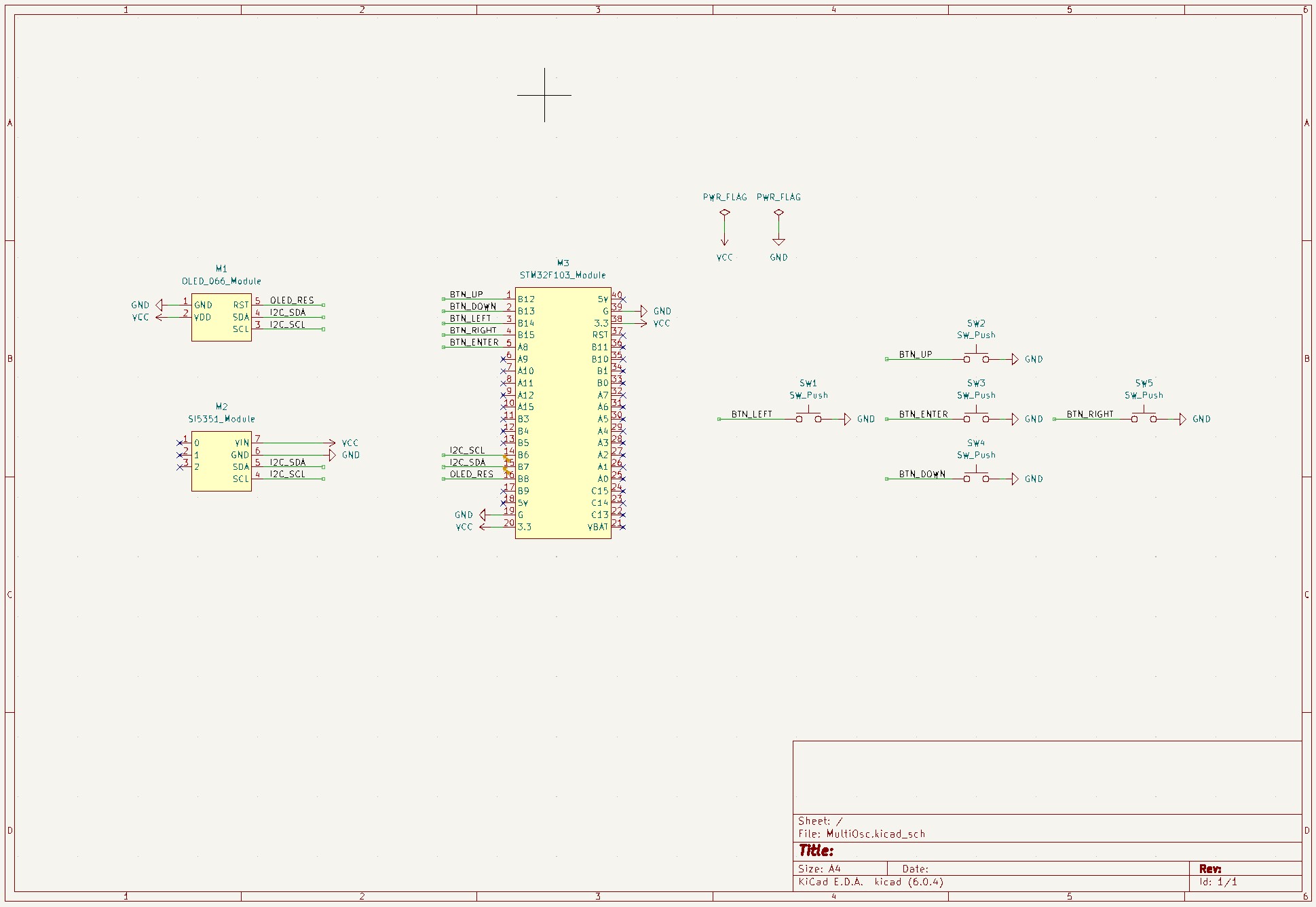
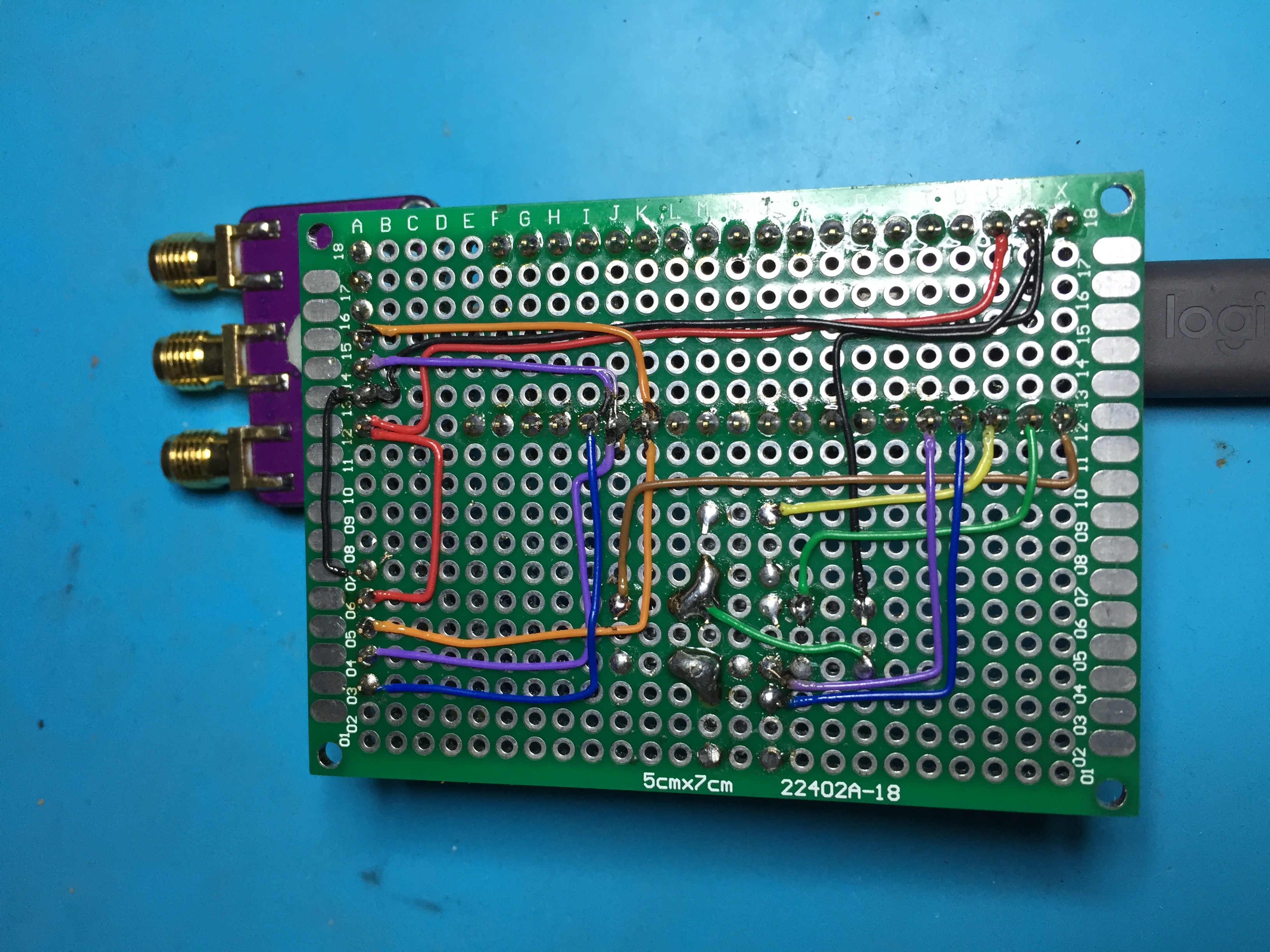
I also have included a very basic PCB to construct the device but it's not needed at all. I have assembled it using a protoboard and it works really well, but for anyone who wants to make it more robust the PCB is a good option.
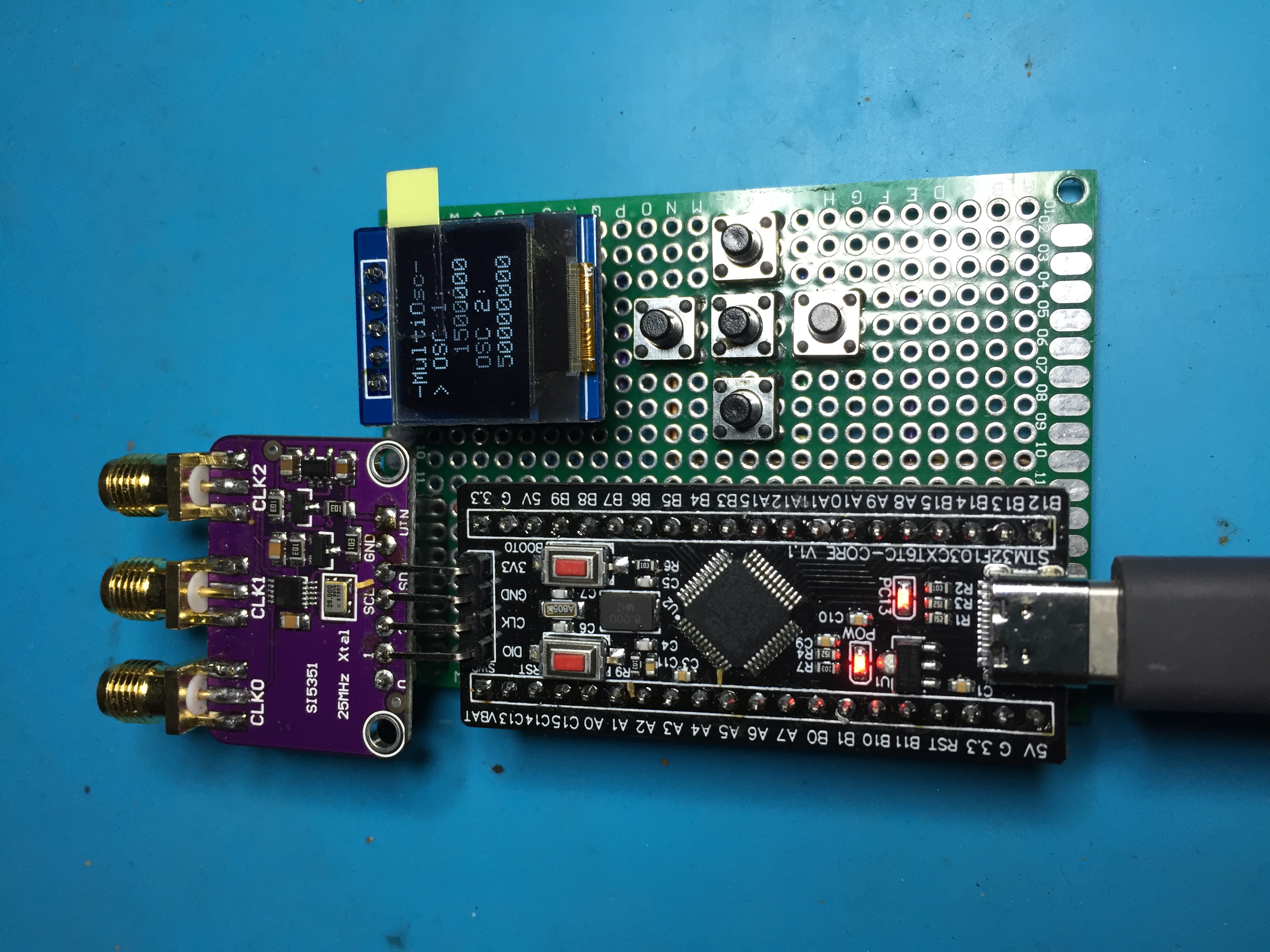
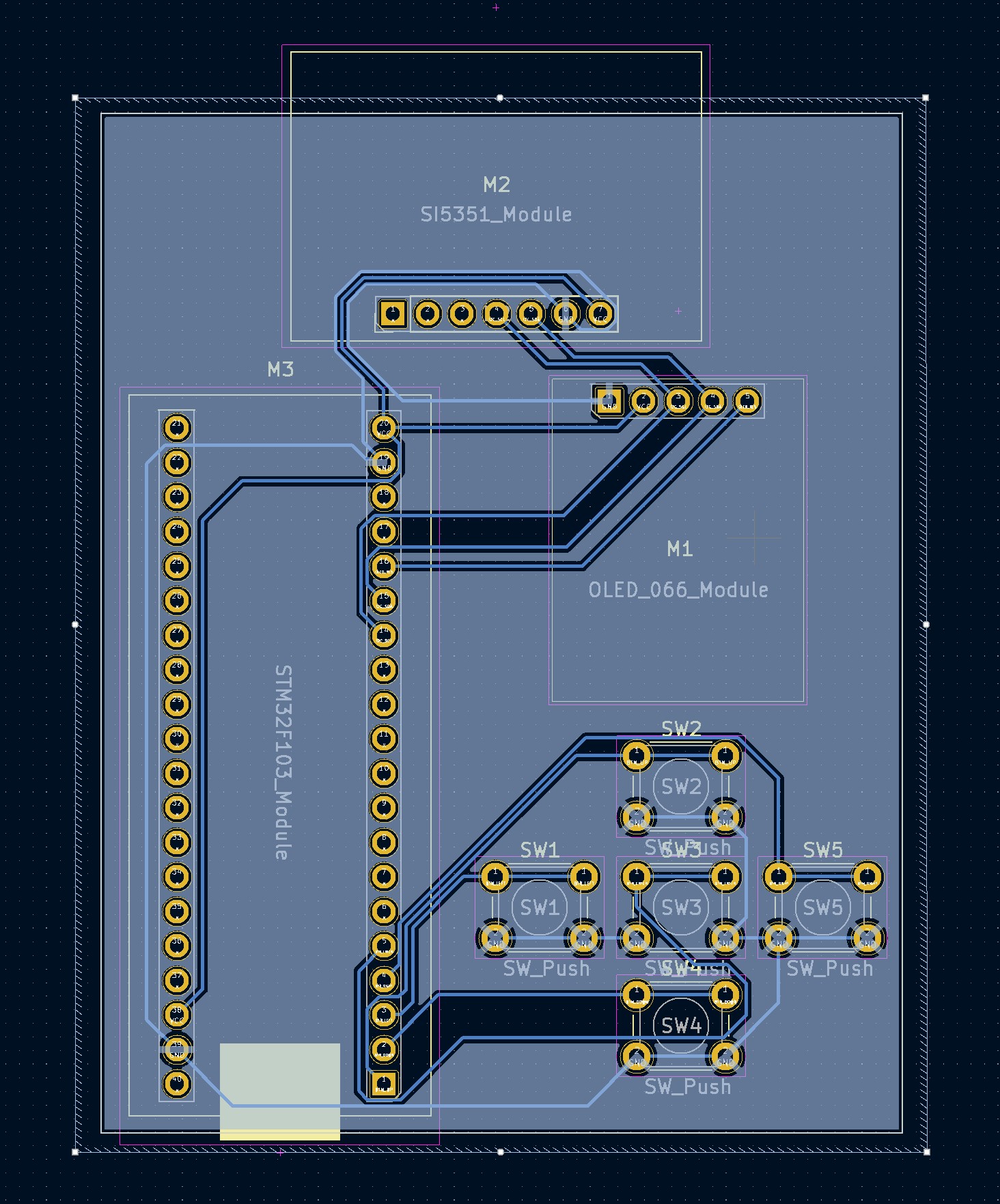
Both, schematic and PCB are included under the "PCB" folder, it's a KiCad 6.0 project and it includes all the custom footprints for the modules in case you want to reuse them.
The bill of materials is very reduced:
I am 99.99999% sure the STM module uses a clone uC, not an original STM device, but as far as I can tell the device works flawlessly.
I have seen a lot of people complaining about the F103 modules failing to run the bootloader, but this is all a missunderstanding on how the bootloader works for the F103.
If you check carefully the AN2606 it clarifies the problem and is really simple, the STM32F10XXX family only has UART bootloader and the modules connect the USB connector to the USB pins from these devices, there is no integrated serial-to-usb converter so the bootloader will not work connecting only the USB port, you also need a serial-to-usb converter and connect it to pins PA9 and PA10, with this the device will be accessible from STM32CubeProgrammer.
In any case I recommend to use a ST-LINK/V2 or similar (I have an original one and a clone, both work but the original one is less prone to cause errors and can be upgraded, so if you can, buy an original one), it works a lot faster and allows to debug the code in real time.
The firmware project is a STM32CubeIde project, currently I have used the 1.9.0 version and it uses the standard drivers and two heavily modified libraries.
The first library is the SSD1306 library by afiskon and you can find the original here: https://github.com/afiskon/stm32-ssd1306 The second library is the SI5351 library by MR-DOS and you can find the original here: https://github.com/MR-DOS/Si5351-lib
As you can imagine the firmware itself is very simple, it creates a menu where you can change the two output frequencies and that's all, nothing else is needed, and as it relies on the two aforementioned libraries controlling the screen and the SI module is a breeze.
Beware that I found there is a problem with CubeMX, if you open the CubeMX file to reconfigure the HAL drivers, pinout or whatever the CubeMX does break the I2C configuration, for the F103 device it does not allow to configure the port speed and without the configuration the I2C bus does not work. If you need to reconfigure the hardware, after re-generating the files you will need to modify the file "stm32f1xx_hal_msp.c" and add to the I2C initialization, before the "HAL_GPIO_Init" call, this:
GPIO_InitStruct.Speed = GPIO_SPEED_FREQ_HIGH;Have fun!
| Qty | Value | Footprint | References |
|---|---|---|---|
| 5 | SW_Push | Button_Switch_THT:SW_PUSH_6mm_H7.3mm | SW1, SW2, SW3, SW4, SW5 |
| 1 | OLED_066_Module | MultiOscFootprints:OLED_066_Module | M1 |
| 1 | SI5351_Module | MultiOscFootprints:SI5351_Module | M2 |
| 1 | STM32F103_Module | MultiOscFootprints:STM32F103_Module | M3 |
It measures 59 × 75 mm and has 2 copper layers, 1.6 mm thick.
8 parts. The full list of its parts is on this page, with links to each part's symbol and footprint where PCBKit's library has them.
From the gusmanb/multiosc repository on GitHub, at the commit this page was made from: the board is PCB/MultiOsc.kicad_pcb and its schematic PCB/MultiOsc.kicad_sch. PCBKit opens the board in the browser, with nothing to install.
Its repository publishes it under the MIT licence: you may reuse it on that licence's terms (keep the author's notice, and for a copyleft licence share your changes alike).

joeycastillo/Sensor-Watch
A board replacement for the classic Casio F-91W wristwatch

rusefi/rusefi
rusefi - GPL internal combustion engine control unit

hoglet67/RGBtoHDMI
Bare-metal Raspberry Pi project that provides pixel-perfect sampling of Retro Computer RGB/YUV video and conversion to HDMI

shanteacontrols/OpenDeck
A platform for building interactive control and sensing devices using MIDI and OSC built with Zephyr RTOS.

hackclub/OnBoard
💡 Join 1,000 teenagers and make your first PCB with a $100 grant!

dangiu/PicoMemcard
Emulating PSX Memory Card (or controller) using a Raspberry Pi Pico

OLIMEX/DIY-LAPTOP
Do It Yourself Open Source Hardware and Software Modular Hacker's Friendly Laptop