


4 layers25.4 × 25.4 mm
Twonkie
dojoe/Twonkie
A USB-PD sniffer/injector/sink based on Google's Twinkie, re-designed to be manufactured by mere mortals.
62 parts415

 gulshanshah/voltshift
An ATmega328P based automatic voltage stable line switcher: senses three incoming mains lines, picks the one holding steady near 240V, and drives a stepper controlled selector onto it, or to OFF when no line is safe.
Voltshift is an open-source printed circuit board by gulshanshah, from the gulshanshah/voltshift repository on GitHub, published under the MIT licence. It is a 2-layer board of 170 × 100 mm with 54 parts on 58 nets, routed with 518 tracks and 43 vias.
It is built around the ATMEGA328P-PU, ULN2003A and BZT52C5V6. Its parts include 21 resistors, 9 capacitors, 5 ICs, 5 diodes and 1 connector. It belongs with the robots and motor control boards and the AVR (ATmega, ATtiny) boards of this library.


Automatic voltage-stable line switcher.
In many villages and homes the supply arrives unbalanced — some lines sit weak, some sit high, and people walk over to the board and move the home supply to the line that behaves. VoltShift does that switching automatically: it watches three incoming lines, picks the one that is stable near 240 V, and drives a selector switch onto it with a stepper motor — or to OFF when no line is safe.
| Path | What it is |
|---|---|
pcb/ | KiCad 9 project — voltshift.kicad_pro, schematic, board and netlist |
firmware/ | ATmega328P firmware (bare-metal C, PlatformIO) |
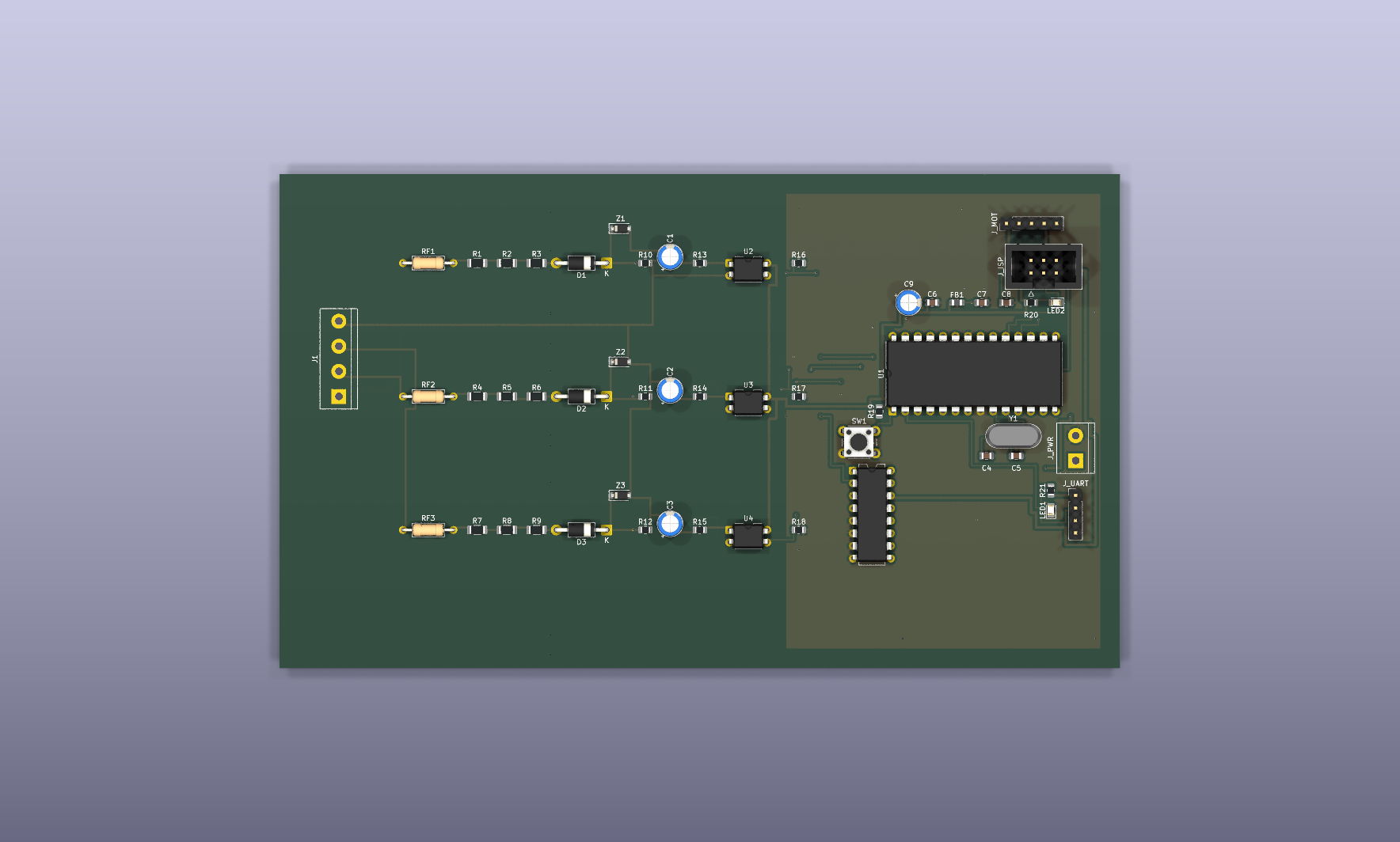
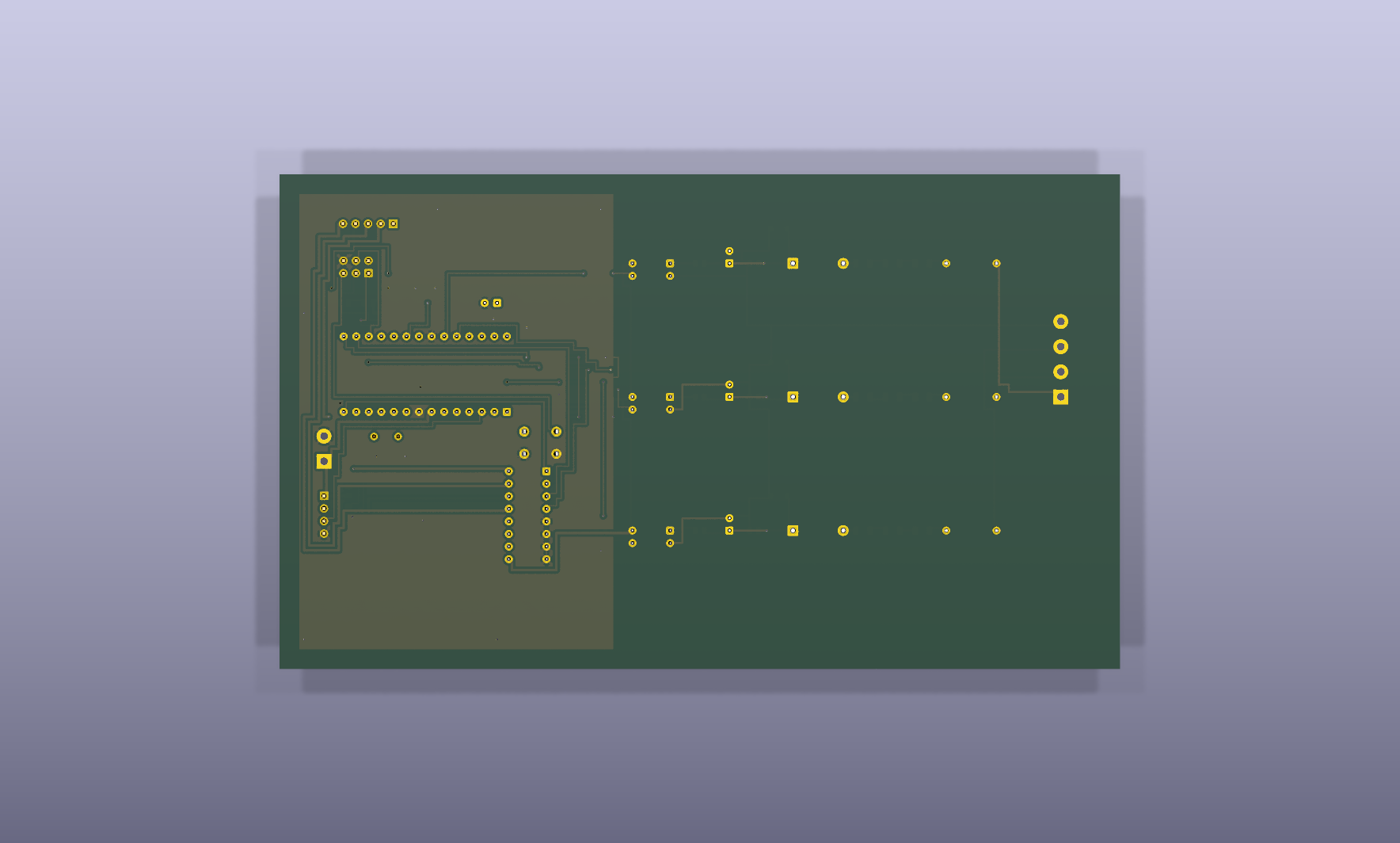
media/ | Board renders, layer plots, schematic SVG and PDF |
docs/ | Schematic PDF and the ERC report |
The board keeps manual switching out of the equation — the home supply always lands on the healthiest voltage.
This board handles 240 VAC mains. Sense resistors must be rated for the working voltage, creepage/clearance must be respected, and the board must not be touched while powered. It is a prototype — validate it against your local electrical rules before putting it anywhere near a real installation.
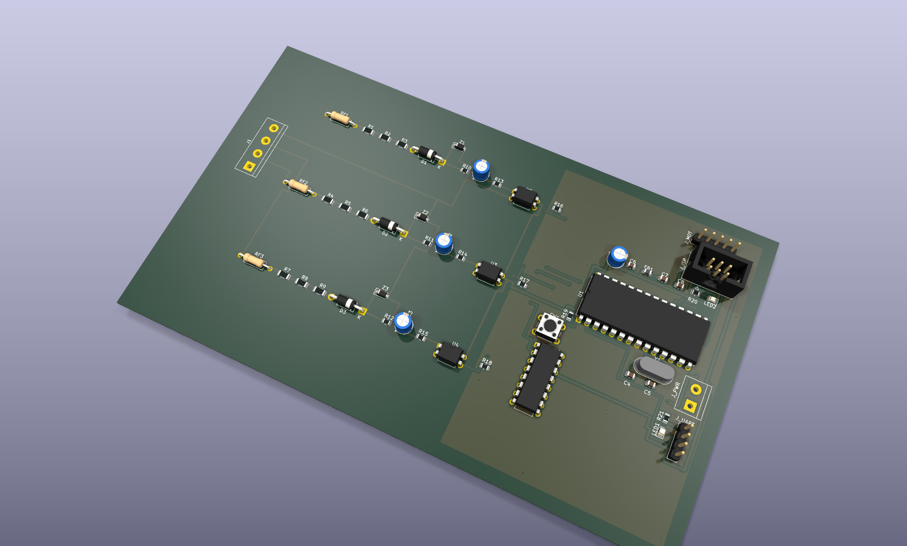
| Top | Bottom |
|---|---|
 |  |
The firmware lives in firmware/ and runs directly on the ATmega328P — no Arduino framework, no communication, fully automatic, about 1.8 KB of flash.
firmware/include/config.h   # thresholds, calibration, pin map, timing
firmware/src/adc.c           # averaged ADC reads + counts-to-decivolts calibration
firmware/src/selector.c      # line validity, best-line choice, hysteresis
firmware/src/stepper.c       # half-step driver for the 28BYJ-48 selector
firmware/src/led.c           # status LED patterns
firmware/src/main.c          # 1 ms tick, sample/evaluate loop, watchdog
Every 10 ms each channel is averaged and converted to decivolts; every 100 ms a line is accepted only if it sits inside 205.0–255.0 V with under 2.0 V of ripple. The selector moves to the accepted line closest to 240 V, only after that line beats the held one by more than 3 V for four consecutive evaluations, and drops to OFF the moment the held line goes invalid. The status LED reports state: slow blink while starting up, solid on a line, fast blink on OFF or while the motor is moving.
Build and flash with PlatformIO:
cd firmware
pio run                     # builds firmware.elf / firmware.hex
pio run -t upload           # default programmer is usbasp (ISP)
Calibration is per-channel in include/config.h — VS_CAL_OFFSET_* and VS_CAL_SPAN_*_PER_100V map raw ADC counts to voltage; tune them against a known-good meter before trusting the decisions.
Open pcb/voltshift.kicad_pro in KiCad 9 and edit the schematic and the board
directly. Run the Electrical Rules Checker after any change — the last check
came back clean (0 errors, 0 warnings).
Keep the two domains apart while editing: mains circuitry stays left of the
isolation gap, the ground pour belongs to the logic side only, and the 6 mm
creepage between them must survive any move. The exported schematic PDF and
the ERC report are in docs/.
Schematic and PCB are done and ERC-clean, and the firmware builds for the ATmega328P. Next up: fab the board and build the first unit.
MIT — see LICENSE.
| Qty | Value | Footprint | References |
|---|---|---|---|
| 9 | 150k 1% | Resistor_SMD:R_1206_3216Metric | R1, R2, R3, R4, R5, R6, R7, R8, R9 |
| 7 | 10k | Resistor_SMD:R_0805_2012Metric | R13, R14, R15, R16, R17, R18, R19 |
| 3 | 100nF | Capacitor_SMD:C_0805_2012Metric | C6, C7, C8 |
| 3 | 1N4007 | Diode_THT:D_DO-41_SOD81_P10.16mm_Horizontal | D1, D2, D3 |
| 3 | 47uF 16V | Capacitor_THT:CP_Radial_D5.0mm_P2.50mm | C1, C2, C3 |
| 3 | 4R7 1W FUSIBLE | Resistor_THT:R_Axial_DIN0207_L6.3mm_D2.5mm_P10.16mm_Horizontal | RF1, RF2, RF3 |
| 3 | 4k7 1% | Resistor_SMD:R_0805_2012Metric | R10, R11, R12 |
| 3 | BZT52C5V6 | Diode_SMD:D_SOD-123 | Z1, Z2, Z3 |
| 3 | PC817 | Package_DIP:DIP-4_W7.62mm | U2, U3, U4 |
| 2 | 1k | Resistor_SMD:R_0805_2012Metric | R20, R21 |
| 2 | 22pF | Capacitor_SMD:C_0805_2012Metric | C4, C5 |
| 1 | +5V TX RX GND | Connector_PinHeader_2.54mm:PinHeader_1x04_P2.54mm_Vertical | J_UART |
| 1 | 10uF 16V | Capacitor_THT:CP_Radial_D5.0mm_P2.50mm | C9 |
| 1 | 16MHz | Crystal:Crystal_HC49-4H_Vertical | Y1 |
| 1 | 28BYJ-48 | Connector_PinHeader_2.54mm:PinHeader_1x05_P2.54mm_Vertical | J_MOT |
| 1 | 5V DC IN | TerminalBlock:TerminalBlock_bornier-2_P5.08mm | J_PWR |
| 1 | ATmega328P-PU | Package_DIP:DIP-28_W15.24mm | U1 |
| 1 | Ferrite 600R@100MHz | Inductor_SMD:L_0805_2012Metric | FB1 |
| 1 | ISP | Connector_IDC:IDC-Header_2x03_P2.54mm_Vertical | J_ISP |
| 1 | MAINS R Y B N | TerminalBlock:TerminalBlock_bornier-4_P5.08mm | J1 |
| 1 | PWR | LED_SMD:LED_0805_2012Metric | LED1 |
| 1 | RESET | Button_Switch_THT:SW_PUSH_6mm | SW1 |
| 1 | STATUS | LED_SMD:LED_0805_2012Metric | LED2 |
| 1 | ULN2003A | Package_DIP:DIP-16_W7.62mm | U5 |
dojoe/Twonkie
A USB-PD sniffer/injector/sink based on Google's Twinkie, re-designed to be manufactured by mere mortals.

Zychlix/Inverter32
An open source, open hardware plug'n'play 3 phase motor inverter design. It

piruetasxyz/kicad-visor-demo
A working example of kicad-visor by piruetas: on every push to main, a GitHub Actions workflow exports every KiCad project in this repository (schematics, board layers, 3D renders and seamlessly looping turntable…

Bouni/BSH-Dev-Board
This project is one of many variants of a PCB that can be used to interface with B/S/H appliances using the awsome bsh-home-appliances project.


Elemirus1996/BitaxeTuner
Automatisches Übertakten, Benchmarken und 24/7-Überwachung für Bitaxe- und NerdAxe-Miner – Windows-App und Server für Raspberry Pi, Windows und Docker: Browser & Handy-App, Push, Pool-Steuerung, Ertrag gegen…

k-takata/PCB_updi_unbricker
UPDI High Voltage programmer for AVR Dx/Ex and ATtiny series

It measures 170 × 100 mm and has 2 copper layers, 1.6 mm thick.
54 parts, built around the ATMEGA328P-PU, ULN2003A and BZT52C5V6. The full list of its parts is on this page, with links to each part's symbol and footprint where PCBKit's library has them.
From the gulshanshah/voltshift repository on GitHub, at the commit this page was made from: the board is pcb/voltshift.kicad_pcb and its schematic pcb/voltshift.kicad_sch. PCBKit opens the board in the browser, with nothing to install.
Its repository publishes it under the MIT licence: you may reuse it on that licence's terms (keep the author's notice, and for a copyleft licence share your changes alike).