
4 layers139.7 × 41.3 mm
Schemat
konrad1s/LineFollower-Kwark
Fast LineFollower Robot project. Build on STM32 F7 microcontroller with custom PCB. Software, Hardware and QT Application.
74 parts12MIT

 GrussmayerLab/fgFocus1
Focus Lock for Micro-Manager
FgFocus is an open-source printed circuit board by GrussmayerLab, from the GrussmayerLab/fgFocus repository on GitHub. It is a 2-layer board of 44.6 × 44.6 mm with 11 parts on 30 nets, routed with 46 tracks and 15 vias.
It is built around the FTSH-105-01-F-DV-P-TR. Its parts include 3 resistors, 2 connectors, 1 capacitor and 1 IC.
fgFocus is an active focus-lock system designed to maintain sharp focus during extended imaging experiments, such as single-molecule and live-cell imaging. It corrects axial drift (movement along the Z-axis) that can occur over time, ensuring your sample stays perfectly in focus.
This project is inspired by similar systems like qgFocus and pgFocus and follows the same naming convention.
Estimated cost for this project is around €160.
fgFocus subfolder. The project was created in KiCad.Gerber.rar archive and select PCB Assembly.bom.csv and fgFocus-top-pos.csv files to complete the assembly configuration.bom_external_components.csv.enclosure directory with a bom.csv to source the enclosure.enclosure directory you can find a REAMDE that explains the assembly of all components.fgFocus.ini file.Install Micro-Manager 2.0
EMU folder (provided) into the root directory of Micro-Manager.Install the EMU Plugin (for editing or customizing the interface)
Install the fgFocus Plugin
FocusLock.jar file into the EMU folder in your Micro-Manager directory.Install the Device Adapter
mmgr_dal_fgFocus.dll file into the root directory of Micro-Manager..h files in the header folder and .cpp files in the source folder..dll file into the Micro-Manager root directory.fgFocus in the root of Micro-Manager.fgFocus and save it in the fgFocus folder. Make sure you select a baudrate of 115200.fgFocus runs on a separate MMCore instance.You should see the following interface:
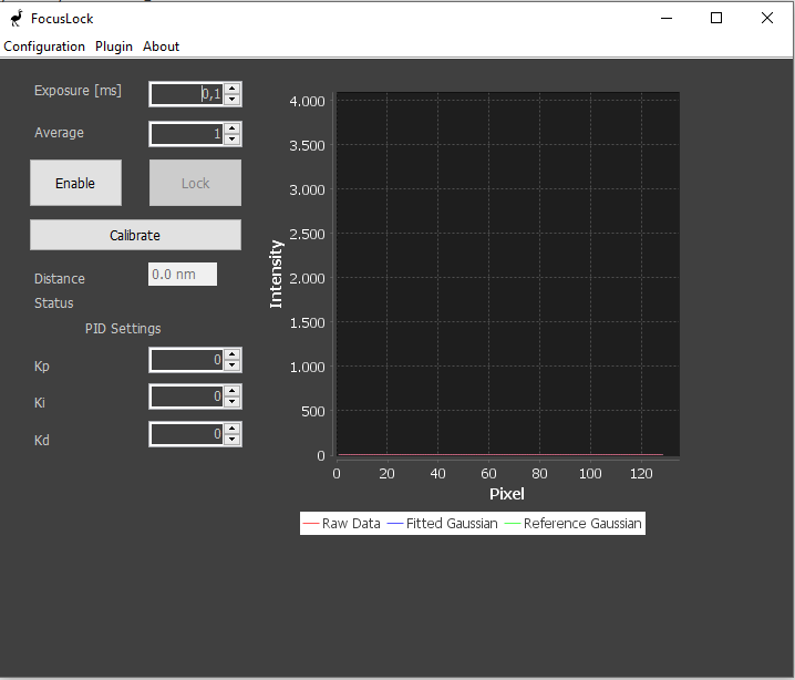
Now you're ready to go!
In the interface:
Enable button to monitor pixel data from the sensor.Calibrate button to run a calibration script that determines the relationship between pixel position and Z-distance.Lock button becomes available, activating the focus lock.Happy Imaging!
To adjust the number of steps or the step size used in the calibration script, open CalibrateTask.java and modify the following variables:
private final int numSteps = 5;
private final double stepSizeUm = 1;Contributions are welcome. Whether you're enhancing firmware stability, refining hardware design, or extending the MicroManager plugins, focused pull requests with clear explanations help keep the project maintainable. Open an issue if you'd like to discuss a feature or improvement before implementing it.
Software in this project is licensed under the MIT License and hardware is licensed under CERN OHL - see LICENSE file for details in the licenses folder.
| Qty | Value | Footprint | References |
|---|---|---|---|
| 4 | MountingHole | MountingHole:MountingHole_3.2mm_M3 | H1, H2, H3, H4 |
| 2 | 10k | Resistor_SMD:R_0805_2012Metric | R6, R7 |
| 1 | 1.5k | Resistor_SMD:R_0805_2012Metric | R5 |
| 1 | 100p | Capacitor_SMD:C_0805_2012Metric | C15 |
| 1 | Conn_02x06_Counter_Clockwise | Connector_Hirose:Hirose_DF11-12DP-2DSA_2x06_P2.00mm_Vertical | J3 |
| 1 | FTSH-105-01-F-DV-P-TR | FTSH-105-01-F-DV-P-TR:SAMTEC_FTSH-105-01-F-DV-P-TR | J1 |
| 1 | XIAO-SAMD21-SMD | Seeed Studio XIAO Series Library:XIAO-SAMD21-SMD | U7 |
It measures 44.6 × 44.6 mm and has 2 copper layers, 1.6 mm thick.
11 parts, built around the FTSH-105-01-F-DV-P-TR. The full list of its parts is on this page, with links to each part's symbol and footprint where PCBKit's library has them.
From the GrussmayerLab/fgFocus repository on GitHub, at the commit this page was made from: the board is PCB/fgFocus/fgFocus.kicad_pcb and its schematic PCB/fgFocus/fgFocus.kicad_sch. PCBKit opens the board in the browser, with nothing to install.
Its repository states no licence, so its author keeps all rights: ask GrussmayerLab before reusing the design.
konrad1s/LineFollower-Kwark
Fast LineFollower Robot project. Build on STM32 F7 microcontroller with custom PCB. Software, Hardware and QT Application.

buckles3636/EasyBLDC
Please ensure your designs meet common standards and include necessary documentation and comments.


BigBroBob2/bat_tag_nrf5340dk
A custom-designed device to record free-flying bat kinematics, echos, and eye movement

zenglhardt/millimobile-platform
This repo contains the KiCad PCB design files for the development board verison of the MilliMobile. For more information on the platform, see the project page

google/mozc-devices
Circuit diagrams and firmware source code for Gboard DIY keyboards


FrameworkComputer/ExpansionCards
Reference designs and documentation to create Expansion Cards for the Framework Laptop