4 layers61.4 × 18.6 mm
Micarry 8ch camera
grufkork/micarray
This design is developed for the Build-Your-Own Ambisonic Microphone Arrays project, where you can also find more information regarding processing of the resulting recordings.
68 parts1MIT
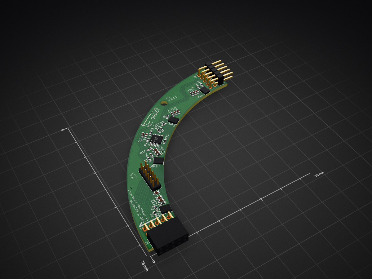
 grufkork/micarray1
This design is developed for the Build-Your-Own Ambisonic Microphone Arrays project, where you can also find more information regarding processing of the resulting recordings.
Micarray is an open-source printed circuit board by grufkork, from the grufkork/micarray repository on GitHub, published under the MIT licence. It is a 4-layer board of 75 × 75 mm with 37 parts on 34 nets, routed with 307 tracks and 37 vias.
It is built around the 74LCX125MTCX and IM73D122V01XTMA1. Its parts include 13 resistors, 11 capacitors, 5 inductors, 3 connectors and 1 IC.


This is an inexpensive 16-channel MEMS microphone array for recording spatial audio made in KiCad 8.0. It can be used for creating immersive audio/video content, locating mechanical faults, tracking moving objects in a room and more.
This design is developed for the Build-Your-Own Ambisonic Microphone Arrays project, where you can also find more information regarding processing of the resulting recordings.
The array consists of four identical boards connected in a circle, allowing for low manufacturing costs (<100$ total, assembly included). These are then placed around an acoustically occluding sphere, emulating a persons head and allowing for generating realistic spatial audio.


The array is connected to the MiniDSP MCHStreamer Lite sound card which receives and digitises the 8x PDM output (the non-lite version should work too, but has not been tested).
| Directory | Contents |
|---|---|
| micarray | 16ch microphone array, main design. Contains KiCAD project files and some exported models and visualisations. |
| imgs | Images for this document |
| micarray_8ch_camera | Unfinished 8ch version for a 360° camera. |
| 3dcammodel | 3D-scan of 360° camera and visualisations |
Production files are generated using JLC Fabrication Toolkit plugin for KiCad 8.0. All parts have LCSC Part #-fields so they can be assembled by JLC, but I would still recommend double checking everything, in particular small & cheap components so they have not gotten low availability. The full array consists of 4 quarter pieces connected in a circle. JLC minimum order size is 5, but having an extra module at hand has proven to be useful as all our orders have always had one mic with worsened performance. Whether this is due to JLC:s manufacturing process, errors in manufacturing, damages during transport or just bad luck is not known.
*This part is not mandatory for basic function, but if you want a precise, snug fit with exact distances between each microphone it is required. There will otherwise be a small gap between each board. **
Due to the tight space constraints, the headers connecting the boards to each other need to be trimmed. First remove the plastic holding the male header pins together, preferably by locally applying heat with a hot air gun and with pliers gently but decisively sliding the softened plastic off along the pins. Using a soldering iron or similar to try to melt plastic off is not recommended, as the residual plastic will fuse with the pins and form a thin insulating surface, which then needs to be sanded off. Be carful trying to cut the plastic into smaller parts, as this might bend the pins.
You can then try connecting the boards, noting how large the gap between them is (should be a couple of millimeters). Disconnect the boards and clip off the male pins so that the boards connect flush, edge-to-edge.
On each of the boards there is a vertical 2mm 12-pin header. This is to be connected to J3 on the MCHStreamer (check page 2 of the datasheet). Note how the pins are mirrored, so they can be connected "towards" each other. As such, a 2x6 pin cable can be used. Which header is used only affects which mic is #1. Specifically, the first mic on the board opposite the connector will be channel 1.

To interface with the array, upload the 16ch PDM firmware to the MCHStreamer.
The 16 mics are evenly spaced in a circle with 60.743mm radius. The array is made to fit on a 60mm sphere. The M3 mounting holes are 71.692mm out, 3.2mm in diameter, 27.1° counter-clockwise relative board edge.
The mics used are the Infineon IM73D122V01. They appear to currently be the best-performing MEMS mics available, using a novel double-membrane technology. Frustratingly, these have a slightly larger footprint with a different pad order than most other similar MEMS mics on the market, so be wary if swapping them for a different model.
The stable branch is the main, cleaned-up version of the old development shrinkening branch.
The primary problem you may experience is massive amounts of noise on one or several channels. This appears to be caused by the clock signal from the MCHStreamer ringing (overshooting) strongly. To prevent this, a 150pF capacitor is included in the design, connected between ground and the clock input. However, if you are still experiencing problems, soldering on some additional capacitance between GND and PDM_CLK-IN on the backside of one of the inter-board headers should resolve the issue. This fix is visible in the second image above, being the two yellow wires sticking out from one of the connectors.
The 8ch version is an old, untested version of the 16ch for recording spatial audio with a 360° camera. It is not tested, but might work with some extra capacitance between GND and PDM_CLK-IN.

| Qty | Value | Footprint | References |
|---|---|---|---|
| 13 | 33 | Resistor_SMD:R_0603_1608Metric_Pad0.98x0.95mm_HandSolder | R1, R2, R3, R4, R5, R6, R7, R8, R9, R10, R11, R12, R13 |
| 5 | 1000p | Capacitor_SMD:C_0603_1608Metric_Pad1.08x0.95mm_HandSolder | C1, C3, C5, C7, C9 |
| 5 | 100n | Capacitor_SMD:C_0603_1608Metric_Pad1.08x0.95mm_HandSolder | C2, C4, C6, C8, C10 |
| 5 | 600R | Inductor_SMD:L_0603_1608Metric_Pad1.05x0.95mm_HandSolder | L1, L2, L3, L4, L5 |
| 4 | IM73D122V01XTMA1 | ul_IM73D122V01XTMA1:PG-LLGA-5-2_INF | MK1, MK2, MK3, MK4 |
| 1 | 150p | Capacitor_SMD:C_0603_1608Metric_Pad1.08x0.95mm_HandSolder | C11 |
| 1 | 74LCX125MTCX | Package_SO:TSSOP-14_4.4x5mm_P0.65mm | IC1 |
| 1 | MCHStreamer J3 | Connector_PinHeader_2.00mm:PinHeader_2x06_P2.00mm_Vertical | J3 |
| 1 | Next | Connector_PinHeader_2.54mm:PinHeader_2x05_P2.54mm_Horizontal | J2 |
| 1 | Previous | Connector_PinSocket_2.54mm:PinSocket_2x05_P2.54mm_Horizontal | J1 |
It measures 75 × 75 mm and has 4 copper layers, 1.6 mm thick.
37 parts, built around the 74LCX125MTCX and IM73D122V01XTMA1. The full list of its parts is on this page, with links to each part's symbol and footprint where PCBKit's library has them.
From the grufkork/micarray repository on GitHub, at the commit this page was made from: the board is micarray/micarray.kicad_pcb and its schematic micarray/74LCX125_sheet.kicad_sch. PCBKit opens the board in the browser, with nothing to install.
Its repository publishes it under the MIT licence: you may reuse it on that licence's terms (keep the author's notice, and for a copyleft licence share your changes alike).
grufkork/micarray
This design is developed for the Build-Your-Own Ambisonic Microphone Arrays project, where you can also find more information regarding processing of the resulting recordings.

lwa-project/zcu102_sync_board
Daughter board for a ZCU102 that allows for synchonization signals to be passed in/out


tortellini13/LambdaCam
We wanted to create a low cost acoustic camera to give more people access to the technology. A commercial acoustic camera could cost $10,000+, which is generally way out of budget for most acoustical consultants or…


AzonInc/Doorman
ESP32-S3 based Intercom Gateway (TCS / Koch / Niko / Scantron / Analogue Systems)

