
2 layers120 × 48 mm
PCB auto doser
gabriel-247/auto-doser-aqurium
Project custom aquarium auto-doser berbasis ESP8266/Wemos dan mobile app.
33 parts

 grtwall/carputer-pcb
Combined ESP32 sensor + body controller PCB — KiCad project, Gerbers, schematics, BOM
Sensormodule final is an open-source printed circuit board by grtwall, from the grtwall/carputer-pcb repository on GitHub. It is a 2-layer board of 142.5 × 99.1 mm with 70 parts on 121 nets, routed with 488 tracks and 0 vias.
It is built around the ULN2002A. Its parts include 18 resistors, 10 connectors, 9 diodes, 5 ICs and 1 capacitor. It belongs with the sensors and measurement boards and the ESP32 boards of this library.
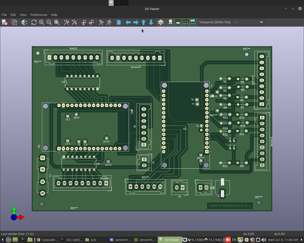
Single 2-layer PCB with dual Feather ESP32s for the Carputer project. Designed for OBD1 vehicles (pre-1996, all makes) — taps into sensor voltages, switch signals, and diagnostic pins directly. No CAN bus required. CAN/OBD2 is an easy add — just a firmware update and an external CAN module (e.g. MCP2515 via SPI).
| Feature | Description |
|---|---|
| Board | 160×120mm, 2-layer FR-4, through-hole assembly |
| MCUs | 2× ESP32 DevKit V1 (sensor + body controller) |
| Power | 12V automotive → DC-DC buck → 3.3V rail |
| Relay drivers | 2× ULN2003A (DIP-16), 7 darlington pairs each |
| Connectors | 3× WAGO 8-way for vehicle harness, 2-way for power |
| Slot | Module | Role | IP | Protocol |
|---|---|---|---|---|
| J5 | Sensor ESP32 | ECU tapping, door switches, DTC | 192.168.4.20 (STA) | UDP 5001/5002/5003 |
| J6 | Body ESP32 | Relays, HVAC, joypad | 192.168.4.1 (AP) | TCP 5000 |
| ULN2003A #1 | ULN2003A #2 |
|---|---|
| Door lock (GPIO 25) | HVAC relay (GPIO 2) |
| Window up (GPIO 26) | AC compressor (GPIO 4) |
| Window down (GPIO 27) | Remote start (GPIO 5) |
| Interior light (GPIO 32) | Fan speed 2 (GPIO 12) |
| Door chime (GPIO 33) | Fan speed 1 (GPIO 18) |
| File | Description |
|---|---|
sensormodule final.kicad_pro | KiCad project |
sensormodule final.kicad_sch | Schematic |
sensormodule final.kicad_pcb | PCB layout |
PCB_PLAN.md | Full design plan |
build_plan.md | THT assembly build plan |
product_description.md | Product overview |
voltage_divider_circuit.txt | ECU voltage divider circuit & wiring |
carputerpcb.png | PCB render preview |
*-Cu.gbr, *-Mask.gbr, *-Silkscreen.gbr | Gerber files for fabrication |
esp32_sensor_module_bom.csv | Bill of Materials |
Sample-BOM_JLCSMT.xlsx | JLC SMT assembly BOM |
generate_pcb.py | Python PCB generation toolkit |
Send Gerber files (sensormodule final-*.gbr + *job.gbrjob) to any PCB fab (JLCPCB, PCBWay, etc.). Board is 2-layer, 160×120mm.
See voltage_divider_circuit.txt for ECU wiring diagram. Connectors use WAGO 8-way terminal blocks for vehicle harness interface.
This PCB integrates two ESP32 modules that communicate with the head unit software:
| Component | Firmware Repo | Connects To | Protocol |
|---|---|---|---|
| J5 — Sensor ESP32 | esp32_sensor_module | Carputer head unit | UDP 5001 (sensor data), 5002 (commands), 5003 (DTC) |
| J6 — Body ESP32 | esp32_body_controller | Carputer head unit | TCP 5000 (relay/audio commands) |
The head unit can be either:
| Qty | Value | Footprint | References |
|---|---|---|---|
| 8 | 10k | Resistor_THT:R_Axial_DIN0204_L3.6mm_D1.6mm_P5.08mm_Vertical | R1, R4, R6, R8, R10, R12, R14, R16 |
| 8 | 5.8k | Resistor_THT:R_Axial_DIN0204_L3.6mm_D1.6mm_P5.08mm_Vertical | R2, R3, R5, R7, R9, R11, R13, R15 |
| 4 | 1 | Connector_PinHeader_1.00mm:PinHeader_1x01_P1.00mm_Vertical | a, a, a, a |
| 3 | LED | LED_THT:LED_D2.0mm_W4.0mm_H2.8mm_FlatTop | D5, D6, D7 |
| 3 | f | Connector_Wire:SolderWire-0.1sqmm_1x01_D0.4mm_OD1mm | f, rx, tx |
| 2 | 2N2219 | Package_TO_SOT_THT:TO-39-3 | t1, t2 |
| 2 | DEVKIT_V1_ESP32-WROOM-32 | DEVKIT_V1_ESP32-WROOM-32:MODULE_DEVKIT_V1_ESP32-WROOM-32 | U1, U2 |
| 2 | R_Small | Resistor_THT:R_Axial_DIN0204_L3.6mm_D1.6mm_P5.08mm_Horizontal | R17, R18 |
| 2 | SolderWire-0.1sqmm_1x01_D0.4mm_OD1mm | Connector_Wire:SolderWire-0.1sqmm_1x01_D0.4mm_OD1mm | join1, join2 |
| 2 | ULN2002A | ULN2003A:DIL16 | U3, U4 |
| 2 | cap | Capacitor_THT:CP_Radial_D5.0mm_P2.00mm | D2, D4 |
| 2 | x1 | Connector_Wire:SolderWire-0.1sqmm_1x01_D0.4mm_OD1mm | d15, Jd14 |
| 1 | 1N4007 | Diode_THT:D_DO-41_SOD81_P10.16mm_Horizontal | D1 |
| 1 | 5vin | Connector_Wago:Wago_734-132_1x02_P3.50mm_Vertical | J4 |
| 1 | C_Polarized | Capacitor_THT:CP_Radial_D5.0mm_P2.00mm | C1 |
| 1 | Conn_01x02_Pin | Connector_Wago:Wago_734-132_1x02_P3.50mm_Vertical | J13 |
| 1 | Conn_01x06_Socket | Connector_Wire:SolderWire-0.1sqmm_1x06_P3.6mm_D0.4mm_OD1mm | J15 |
| 1 | D_Zener | Diode_THT:D_DO-41_SOD81_P10.16mm_Horizontal | D3 |
| 1 | Fuse | Fuse:Fuseholder_Clip-5x20mm_Eaton_1A5601-01_Inline_P20.80x6.76mm_D1.70mm_Horizontal | F1 |
| 1 | LM7805_TO220 | Package_TO_SOT_THT:TO-220-3_Vertical | U5 |
| 1 | Screw_Terminal_01x02 | Connector_Wago:Wago_734-132_1x02_P3.50mm_Vertical | J5 |
| 1 | Screw_Terminal_01x08 | Connector_Wago:Wago_734-139_1x09_P3.50mm_Vertical | sensor3 |
| 1 | USB_C_Receptacle | Connector_USB:USB_C_Receptacle_XKB_U262-16XN-4BVC11 | J14 |
| 1 | Wago_734-136_1x06_P3.50mm_Vertical | Connector_Wago:Wago_734-136_1x06_P3.50mm_Vertical | sensormodule c3 |
| 1 | body1 | Connector_Wago:Wago_734-139_1x09_P3.50mm_Vertical | body1 |
| 1 | body2 | Connector_Wago:Wago_734-139_1x09_P3.50mm_Vertical | body2 |
| 1 | c | Connector_Wire:SolderWire-0.1sqmm_1x01_D0.4mm_OD1mm | c |
| 1 | d13 | Connector_Wire:SolderWire-0.1sqmm_1x02_P3.6mm_D0.4mm_OD1mm | J12 |
| 1 | joy | Connector_Wago:Wago_734-137_1x07_P3.50mm_Vertical | J6 |
| 1 | ref | Connector_Wire:SolderWire-0.1sqmm_1x01_D0.4mm_OD1mm | J7 |
| 1 | rx | Connector_Wire:SolderWire-0.1sqmm_1x01_D0.4mm_OD1mm | J9 |
| 1 | sensor1 | Connector_Wago:Wago_734-139_1x09_P3.50mm_Vertical | sensor1 |
| 1 | sensor2 | Connector_Wago:Wago_734-139_1x09_P3.50mm_Vertical | sensor2 |
| 1 | tx | Connector_Wire:SolderWire-0.1sqmm_1x01_D0.4mm_OD1mm | J10 |
The 62 most common of 70 parts.
It measures 142.5 × 99.1 mm and has 2 copper layers, 1.6 mm thick.
70 parts, built around the ULN2002A. The full list of its parts is on this page, with links to each part's symbol and footprint where PCBKit's library has them.
From the grtwall/carputer-pcb repository on GitHub, at the commit this page was made from: the board is sensormodule final.kicad_pcb and its schematic sensormodule final.kicad_sch. PCBKit opens the board in the browser, with nothing to install.
Its repository states no licence, so its author keeps all rights: ask grtwall before reusing the design.
gabriel-247/auto-doser-aqurium
Project custom aquarium auto-doser berbasis ESP8266/Wemos dan mobile app.

grtwall/esp32_microsquirt_iobox
ESP32 MicroSquirt I/O box — CAN bridge that turns MS2/Extra's realtime broadcast into fan/IAC/generic outputs, with a GC9A01 round gauge, 29-bit CAN responder, and 0x710 dash broadcast.


siderakb/ergo-snm-keyboard
ErgoSNM is a split ergonomic keyboard integrated with trackball, wireless is in beta

