2 layers19 × 76 mm
Sub
google/mozc-devices
Circuit diagrams and firmware source code for Gboard DIY keyboards
15 parts3kApache-2.0
 GronuJ/bikesensor2
Geo-tagged bike vibration analysis. ESP32 + MPU-6050 over BLE, GPX from phone, short-time FFTs aligned to ~2 m of road via clock-model + GPS interpolation.
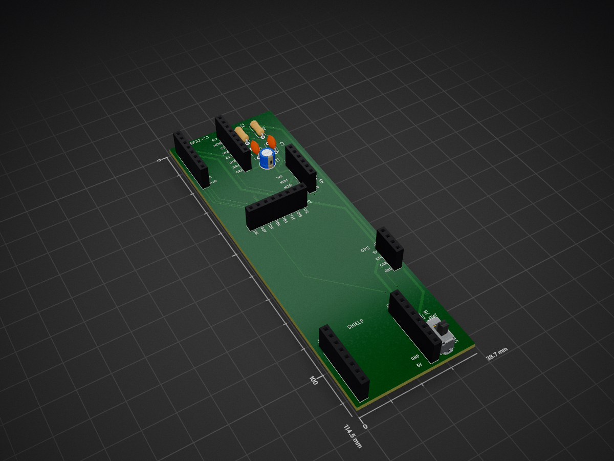
Bikesensor pcb is an open-source printed circuit board by GronuJ, from the GronuJ/bikesensor repository on GitHub. It is a 2-layer board of 38.7 × 114.5 mm with 15 parts on 37 nets, routed with 111 tracks and 16 vias.
Its parts include 8 connectors, 3 capacitors, 3 resistors and 1 switch. It belongs with the radio and wireless boards and the ESP32 boards of this library.
A standalone, low-cost, pure IoT hardware and software mapping pipeline for geo-tagged bike vibration and road-quality analysis.
bikesensor turns an ESP32-C3 SuperMini, an MPU-6050 IMU, a NEO-6M GPS, and an SPI MicroSD card module into a standalone, battery-powered mapping box.
When you ride, the device autonomously records high-frequency (200 Hz) vertical accelerometer vibrations and sparse (1 Hz) GPS coordinate ticks into unified local CSV log files on the SD card. When you return home, the device connects to your home Wi-Fi and uploads all offline ride CSVs over HTTPS to kiel.earth, where the rides are stored, processed and mapped. That website lives in its own repository; this one holds the firmware, the carrier PCB and the enclosure.
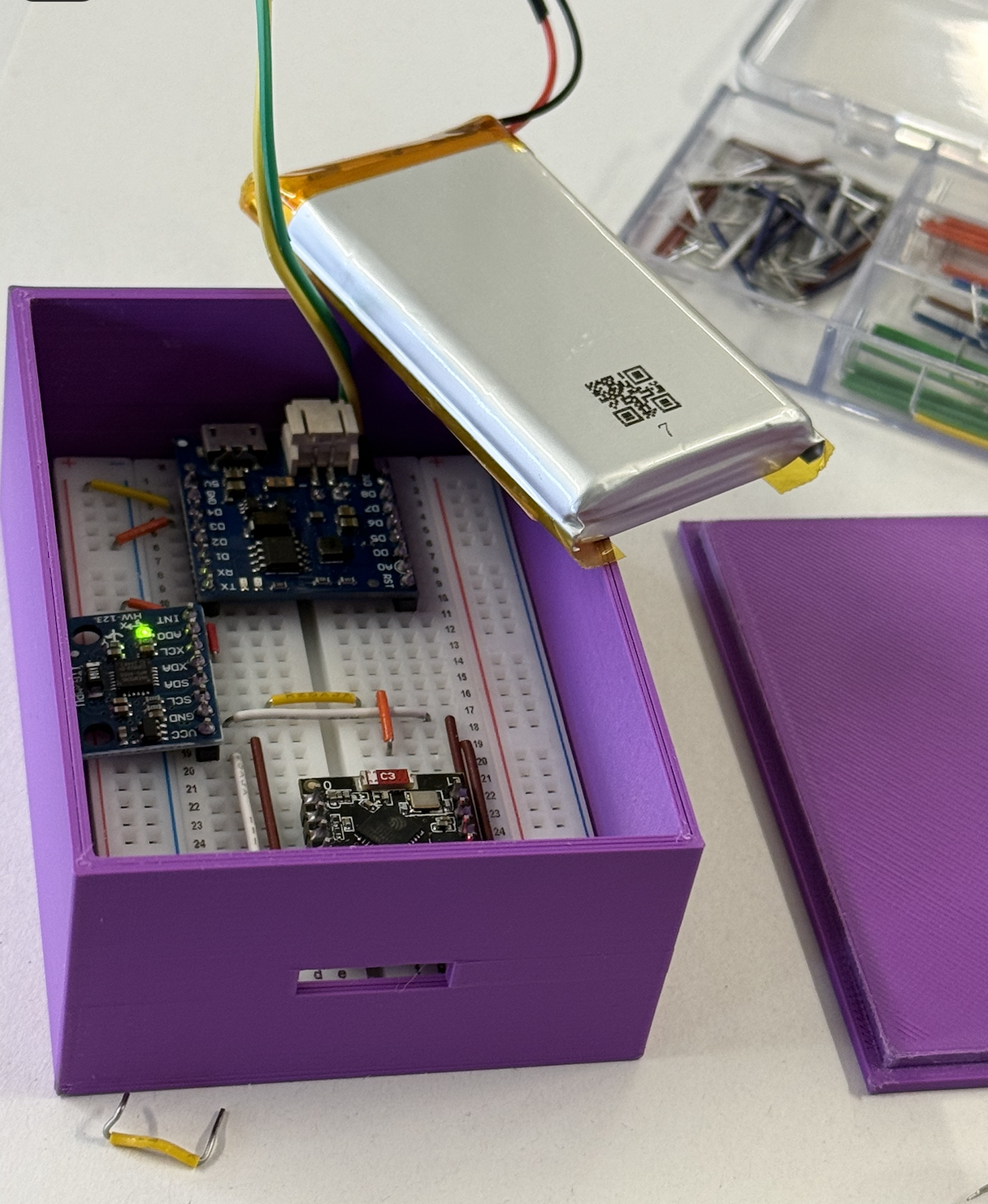
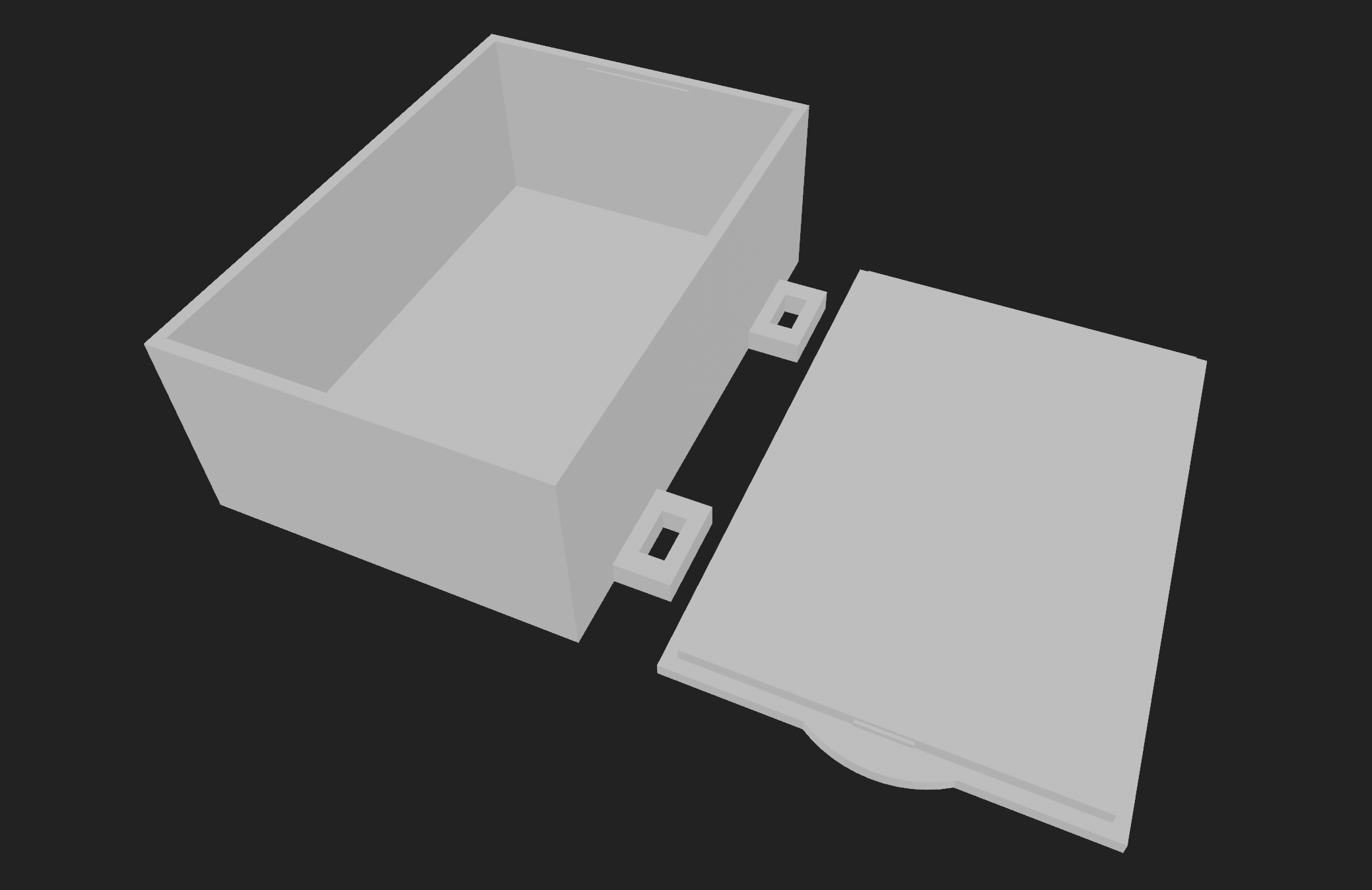
production/bikesensor.zip) but not assembled. Its ESP32 headers were routed against the wrong SuperMini pinout, so every signal lands on a different GPIO than the hand-wired prototype used. The default firmware build is remapped to match the board; the battery sense needs one bodge wire during assembly, and the module must be mounted face down. Details in custom_pcb/PIN_VERIFICATION.md.Below is the completed physical system mounted on a custom 3D-printed handlebar enclosure and its 3D modeling design:
| Physical System | 3D Printed Enclosure Design |
|---|---|
 |  |
flowchart TD
    subgraph Riding [1. Outdoor Bike Ride]
        ESP[ESP32-C3 SuperMini]
        IMU[MPU-6050 Accelerometer 200Hz] --> ESP
        GPS[NEO-6M GPS Module 1Hz] --> ESP
        ESP -->|Log unified CSV| SD[(SPI MicroSD Card)]
    end

    subgraph Home [2. Arrival Home & Wi-Fi Sync]
        ESP_H[ESP32-C3 Home Mode] -->|Connects to home Wi-Fi| Router((Home Router))
        SD -->|Stream CSVs over HTTPS POST| ESP_H
        ESP_H -->|/api/bike/ingest| Site[kiel.earth]
        Site -->|2xx: file is stored| ESP_H
        ESP_H -->|Delete uploaded file| SD
endThe hardware operates on 3.3V logic for standard communication and SD logging, driven by a Wemos D1 Mini TP5400 Battery Shield.
Here is the physical wiring diagram for our custom carrier board:
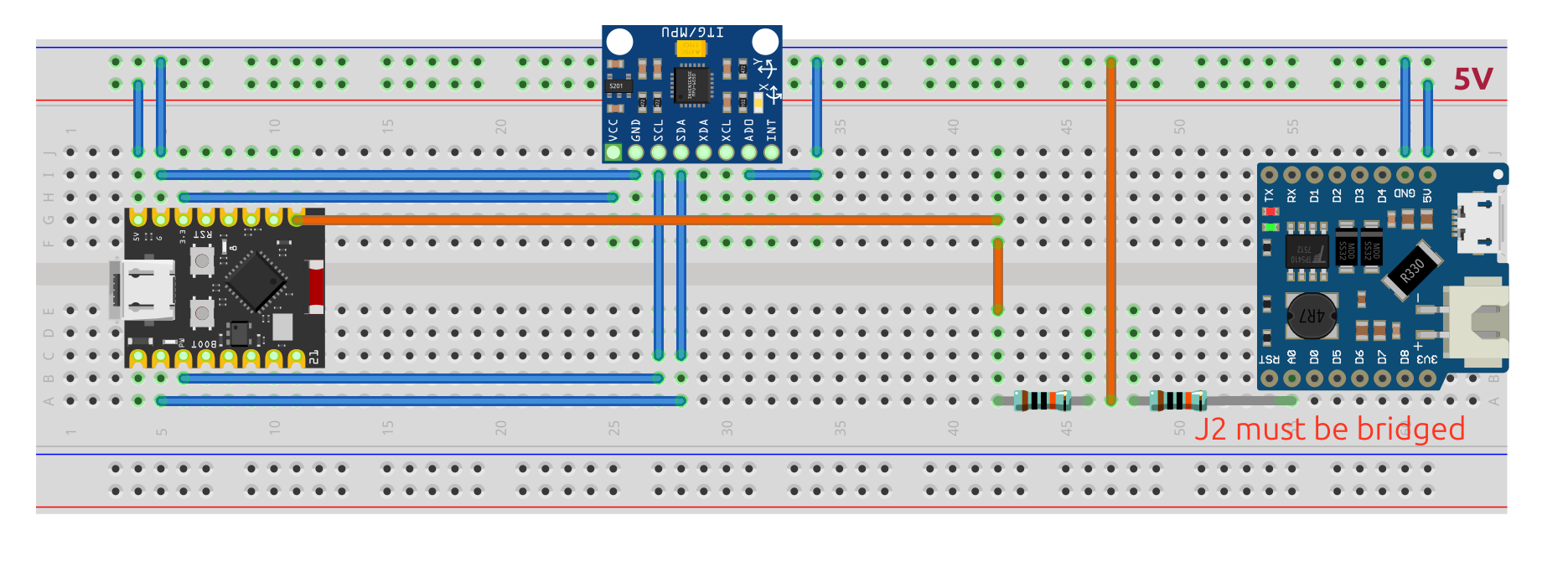
R3 (10 kΩ) pulls SPI_CS to +3V3, keeping the card deselected while the ESP32 boots. The schematic's ESP32 connectors are generic sockets, so it does not show which GPIO each net reaches; the table below does.
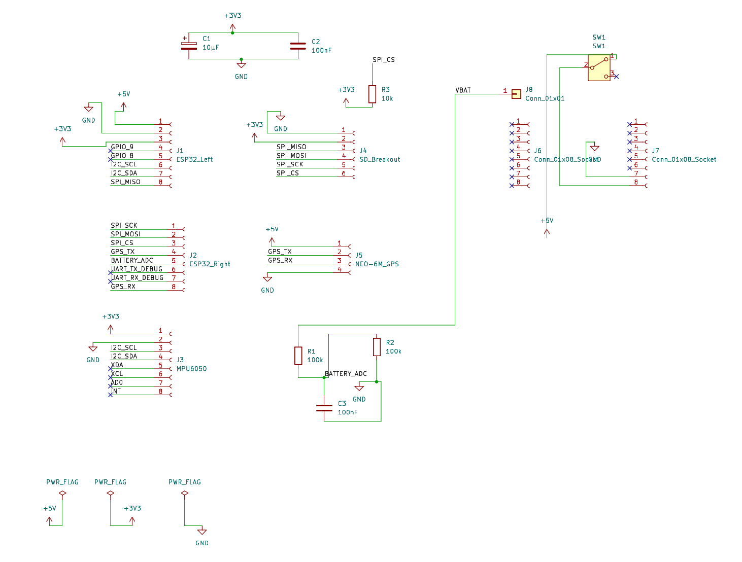
The carrier is 38.74 × 114.47 mm, 2-layer, all through-hole. Every connected pin carries a silkscreen signal name — GTX/GRX are the GPS UART, DTX/DRX the debug UART, and ADC the battery divider.
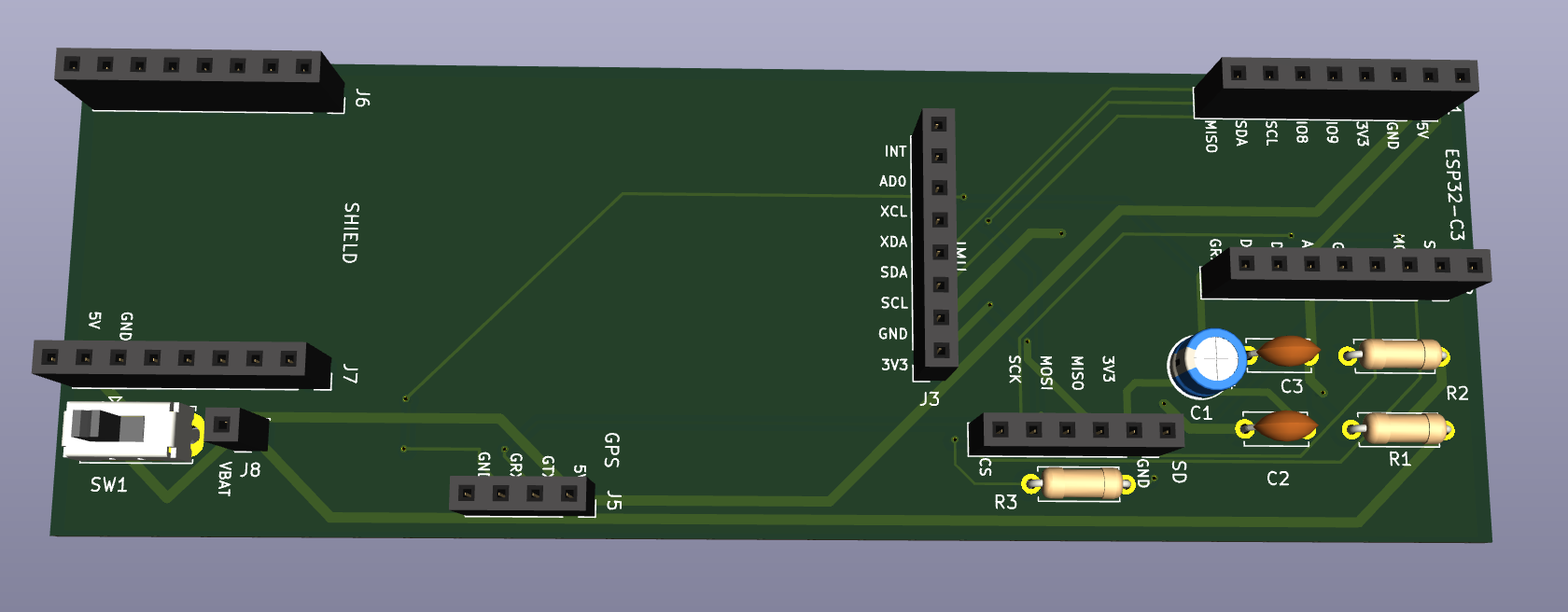
GPIOs are for the carrier PCB (default firmware build). The hand-wired prototype used different ones — pio run -d firmware -e handwired.
| Peripheral | Connection | Pin | Notes |
|---|---|---|---|
| MPU-6050 (I2C) | SDA | GPIO 1 | J1.7, shared I2C bus |
| SCL | GPIO 2 | J1.6. Strapping pin, held high by the GY-521's pull-ups | |
| VCC / GND | 3V3 / GND | Powered by system 3.3V rail | |
| MicroSD (SPI) | CS | GPIO 7 | J2.3, R3 pull-up |
| MOSI | GPIO 6 | J2.2 | |
| SCK | GPIO 5 | J2.1 | |
| MISO | GPIO 0 | J1.8 | |
| VCC / GND | 3V3 / GND | Powered by system 3.3V rail | |
| NEO-6M (UART1) | TX / RX | GPIO 8 / GPIO 21 | J2.4 / J2.8. Firmware detects which one the GPS transmits on |
| VCC / GND | 5V / GND | Powered by 5V boost output | |
| Wemos Battery Shield | 5V Out | J7 Pin 8 | Boosted 5.0V output |
| GND | J7 Pin 7 | System Ground | |
| SPDT Slide Switch (SW1) | In / Out | In Series | Connected between J7 Pin 8 (5V out) and 5V net (ESP32 5V pin). Completely cuts off system power while preserving USB charging. |
| Voltage Divider (R1, R2, C3) | Junction | GPIO 3 | Routed to J2.5 = GPIO 9, which has no ADC; reaches GPIO 3 only via the bodge wire in PIN_VERIFICATION.md. R1 (100kΩ) and R2 (100kΩ) divide raw battery voltage in half (4.2V -> 2.1V) for safe ADC reading. C3 (100nF) in parallel with R2 filters noise. |
| Decoupling Caps (C1, C2) | Parallel | 3V3 / GND | C1 (47µF radial; 10µF fits but is marginal) and C2 (100nF ceramic) placed in parallel next to the MicroSD socket prevent write-cycle voltage sags. |
The firmware resides in firmware/bikesensor/bikesensor.ino and compiles out-of-the-box.
To protect your home Wi-Fi passwords from being committed to Git, create a file named private_credentials.h inside firmware/bikesensor/:
#pragma once
#define WIFI_SSID "YourHomeSSID"
#define WIFI_PASS "YourHomePassword"
#define SERVER_HOST "kiel.earth"
#define SERVER_PORT 443
#define SERVER_UPLOAD_PATH "/api/bike/ingest"
#define DEVICE_TOKEN "your-device-token"   // sent as: Authorization: Bearer <token>
The firmware preprocessor will automatically detect and include this file during compile, keeping your passwords safe and isolated in your local workspace.
pio run -d firmware              # Build firmware binary
pio run -d firmware -t upload    # Flash to ESP32-C3 (Serial port is auto-detected)
pio device monitor -b 115200 # Real-time console debuggerThe logging box talks to the website over a single HTTPS endpoint.
When writing to the MicroSD card, the device registers data in a unified, comma-separated format:
millis,ax,ay,az,lat,lon,ele,speed_kmh,battery_pct,gps_timemillis: Relative milliseconds from ESP32 boot (used to align high-frequency vibration data).ax,ay,az: Raw vertical/lateral/longitudinal accelerometer values (the ±4 g scale, 1/8192, is applied on the website, not on the device).lat,lon,ele,speed_kmh: GPS coordinate details.battery_pct: Divided battery measurement (0 - 100%) read from GPIO 3 on the carrier PCB (GPIO 0 on the hand-wired prototype).gps_time: GPS UTC timestamp (used as a clock reference).When the ESP32-C3 boots in Wi-Fi sync mode upon returning home, it uploads every ride file on the SD card, one HTTPS request each:
POSThttps://kiel.earth/api/bike/ingest (set by SERVER_HOST / SERVER_UPLOAD_PATH)Content-Type: text/csv, Authorization: Bearer <DEVICE_TOKEN>, X-Ride-Id: <filename without .csv>The device deletes a file from the SD card only after a 2xx response. On a timeout, TLS failure or any other status it keeps the file and retries on the next sync.
| Qty | Value | Footprint | References |
|---|---|---|---|
| 2 | 100k | Resistor_THT:R_Axial_DIN0207_L6.3mm_D2.5mm_P7.62mm_Horizontal | R1, R2 |
| 2 | 100nF | Capacitor_THT:C_Disc_D5.0mm_W2.5mm_P5.00mm | C2, C3 |
| 2 | Conn_01x08_Socket | Connector_PinSocket_2.54mm:PinSocket_1x08_P2.54mm_Vertical | J6, J7 |
| 1 | 10k | Resistor_THT:R_Axial_DIN0207_L6.3mm_D2.5mm_P7.62mm_Horizontal | R3 |
| 1 | 10µF | Capacitor_THT:CP_Radial_D5.0mm_P2.00mm | C1 |
| 1 | Conn_01x01 | Connector_PinSocket_2.54mm:PinSocket_1x01_P2.54mm_Vertical | J8 |
| 1 | ESP32_Left | Connector_PinSocket_2.54mm:PinSocket_1x08_P2.54mm_Vertical | J1 |
| 1 | ESP32_Right | Connector_PinSocket_2.54mm:PinSocket_1x08_P2.54mm_Vertical | J2 |
| 1 | MPU6050 | Connector_PinSocket_2.54mm:PinSocket_1x08_P2.54mm_Vertical | J3 |
| 1 | NEO-6M_GPS | Connector_PinSocket_2.54mm:PinSocket_1x04_P2.54mm_Vertical | J5 |
| 1 | SD_Breakout | Connector_PinSocket_2.54mm:PinSocket_1x06_P2.54mm_Vertical | J4 |
| 1 | SW1 | Button_Switch_THT:SW_Slide_SPDT_Straight_CK_OS102011MS2Q | SW1 |
It measures 38.7 × 114.5 mm and has 2 copper layers, 1.6 mm thick.
15 parts. The full list of its parts is on this page, with links to each part's symbol and footprint where PCBKit's library has them.
From the GronuJ/bikesensor repository on GitHub, at the commit this page was made from: the board is custom_pcb/bikesensor_pcb/bikesensor_pcb.kicad_pcb and its schematic custom_pcb/bikesensor_pcb/bikesensor_pcb.kicad_sch. PCBKit opens the board in the browser, with nothing to install.
Its repository states no licence, so its author keeps all rights: ask GronuJ before reusing the design.
google/mozc-devices
Circuit diagrams and firmware source code for Gboard DIY keyboards

hoglet67/RGBtoHDMI
Bare-metal Raspberry Pi project that provides pixel-perfect sampling of Retro Computer RGB/YUV video and conversion to HDMI

mntmn/amiga2000-gfxcard
MNT VA2000, an Open Source Amiga 2/3/4000 Graphics Card (Zorro II/III), written in Verilog

hackclub/OnBoard
💡 Join 1,000 teenagers and make your first PCB with a $100 grant!

kenp-io/not-for-airpods-repairs
The content of this repository is licensed under the WTFPL License. Please have a close look at the terms before using this material.

Luos-io/luos_engine
Open-source and real-time orchestrator for cyber-physical-systems, to easily design, test and deploy embedded applications and digital twins.

Chrismettal/EleLab_v2
Cheap DIY lab system for hobbyists and the tinkering folk
