

2 layers65 × 56 mm

Contains the KiCad design files and files for 3D printing the case of the board.
Macro pad is an open-source printed circuit board by Grilled-Cheese-Engineering, from the Grilled-Cheese-Engineering/3x3MacroPadExtras repository on GitHub, published under the GPL-3.0 licence. It is a 2-layer board of 61 × 80.5 mm with 23 parts on 34 nets, routed with 98 tracks and 9 vias.
Its parts include 10 switches, 9 diodes, 1 resistor, 1 IC and 1 connector. It belongs with the keyboards and input boards and the nRF52 and nRF5x boards of this library.
Documentation written by JStudios6118
This repository contains the KiCad design files and files for 3D printing the case of the board as well as an assembly guide to build your own.
Download the firmware from our master ZMK Firmware Repository: GCE ZMK Firmware
All of the KiCad files are provided in the the KiCad directory. KiCad Files
Some of the symbols used may not be present. Make sure you have Seeed Studios' XIAO Kicad Symbol Library and ScottoKeebs Kicad Library.
You can find the JLCPCB production ready files in this directory as well. Just download the zip files in the directory and upload to JLCPCB (or any other fabrication service) to order. Production Files
To 3D print the case, use the provided 3MF files in the 3D Printing directory. 3D Printing
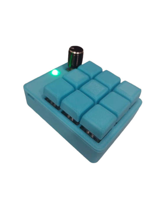
*In our testing, a 600mah battery lasts about 7-9 days using bluetooth.
Building the macro pad is very straightforward as long as you do things in the right order.
Solder the Seeed Studio XIAO board to the pads on the top-left corner of the pcb. The USB-C port should be facing outwards. It is recommended to use an SMD soldering technique such as reflow soldering for this step so the battery pads can be soldered but hand soldering also works at the expense of not having a battery.
WARNING: If soldering the battery pads to the PCB, use less solder paste than you think. It is very easy to bridge the pads and if that happens you will have to desolder the MCU. Trust me, I've had that happen everytime I build one.
Use a multimeter to check for continuity between pins. It is important that there is no bridging between any of the pads. Here is a picture from the schematic showing what pads connect to what parts of the PCB: Wiring Diagram. If ANY pads are bridged you will need to fix them. There should not be continuity between the battery positive and negative holes on the board.
Solder an LED of your choice to the site marked LED. The square pad should be connected to the anode of the LED. Also solder preferably a 1k Ohm Resistor into the site marked R1. Plug in the board to power and the LED should light up. Make sure to snip the leads after doing so.
Next solder the diodes to the board. It is recommended to solder them to the front face of the board. Use the reference on the back of the board to get the correct polarity. Snip the leads close to the board once finished.
Now solder the MX Keyswitches onto the front face of the board. If the switch does not have stabilizers built in, it will be challenging to keep the switches straight. The keyplate piece of the 3D printed files can help keep the switches aligned if that is the case.
Finally solder the EC11 Rotary Encoder to the PCB on to the front face. It is recommended to solder the mounting pins first to help hold the rotary encoder in place while soldering the other pins.
Solder the your battery to the site marked J1. Be sure that the battery is connected with the correct polarity and the pins are not bridged. The battery was not soldered previously in the guide to protect it from heat from the soldering iron.
Flash the firmware to the MCU. If this is the first firmware to be flashed to the device, it should pop up in your file manager automatically. If not, double press the small reset button on the MCU. Finally, drag and drop the uf2 file to the device. It will automatically disconnect and reboot. It may give an error when you drop it onto the device but that is normal.
You can download the firmware in the Releases Section of this repository: Firmware Downloads
You can use ZMK Studio to customize the keybindings. Please raise an issue if you have any problems with this guide.
-Grilled Cheese Engineering
| Qty | Value | Footprint | References |
|---|---|---|---|
| 9 | ~ | ScottoKeebs_Scotto:Diode_DO-35 | D1, D2, D3, D4, D5, D6, D7, D8, D9 |
| 9 | ~ | ScottoKeebs_MX:MX_PCB_1.00u | S1, S2, S3, S4, S5, S6, S7, S8, S9 |
| 1 | Conn_01x02 | TestPoint:TestPoint_2Pads_Pitch2.54mm_Drill0.8mm | J1 |
| 1 | LED | LED_THT:LED_D3.0mm | LED |
| 1 | R | Resistor_THT:R_Axial_DIN0204_L3.6mm_D1.6mm_P7.62mm_Horizontal | R1 |
| 1 | RotaryEncoder | Rotary_Encoder:RotaryEncoder_Alps_EC11E-Switch_Vertical_H20mm | SW1 |
| 1 | XIAO-nRF52840-SMD | Seeed_Studio_XIAO_Series:XIAO-nRF52840-SMD | U1 |

google/mozc-devices
Circuit diagrams and firmware source code for Gboard DIY keyboards


Duet3D/Duet-2-Hardware
The KiCAD source for the Duet 3d printer controller see www.duet3d.com
It measures 61 × 80.5 mm and has 2 copper layers, 1.6 mm thick.
23 parts. The full list of its parts is on this page, with links to each part's symbol and footprint where PCBKit's library has them.
From the Grilled-Cheese-Engineering/3x3MacroPadExtras repository on GitHub, at the commit this page was made from: the board is KiCad/macro_pad.kicad_pcb and its schematic KiCad/macro_pad.kicad_sch. PCBKit opens the board in the browser, with nothing to install.
Its repository publishes it under the GPL-3.0 licence: you may reuse it on that licence's terms (keep the author's notice, and for a copyleft licence share your changes alike).