2 layers30 × 41.1 mm
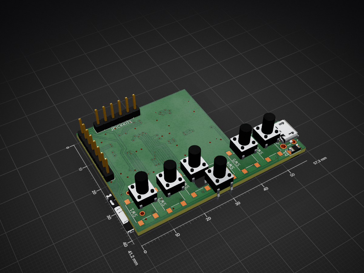
 greengravity/Datakey2
Datakey
Datakeyboard is an open-source printed circuit board by greengravity, from the greengravity/Datakey repository on GitHub. It is a 2-layer board of 57.3 × 41.2 mm with 49 parts on 50 nets, routed with 685 tracks and 109 vias.
It is built around the PIC24FJ128GB204-I/PT, STLQ015M30R and NX2301P, with the BAS40-06 among its other parts. Its parts include 14 resistors, 10 capacitors, 6 switches, 5 transistors and 3 ICs. It belongs with the PIC boards of this library.


In short, it is a physical offline-device to store secret information like account data or banking informations.
While mobile apps can do things like this, its always possible to have some spyware installed with the last gaming app or whatever.
Because of that i dont trust mobiles too much and so i decided to make this little project.
It is pretty simple, the device have 6 Buttons for input and a 1.7" Display for output.
Just enter your pincode and you will be able to browse through your entries.
Every entry have a name and up to 5 additional tokens to store informations like username/password or other things.
You can add/delete or modify entries directly on the device, without the need of a mobile-device or computer.
The tokens itself are entered with a virtual keyboard on the device.
Its like entering the name with a gamecontroller on a gamingconsole.
Everything entered will be encrypted with a masterkey and stored on a micro-sd card.
The masterkey is a secret that only the user know, if it get lost, you may not be able to restore your data anymore.
Usually the masterkey is stored in the device, so you dont need to rember it all the time.
But if you or someone else mess up the pincode verification, the masterkey get deleted from the device (for security reasons).
Thats why it is important to have the masterkey stored or memorized safely.
The Device can also act as an keyboard.
After you connected the device to your pc via usb, you can select an entry/token and push it to the pc.
like entering the data with a keyboard.
This type of communication is pretty much one-way, so the connected system cannot control the output of the device.
It should be safe to use it like that.
Enter the sd-card to the slot on the side of the device and open it.
You will be questioned about the masterkey.
Enter one, the longer the better.
Then you will be questioned about your pincode.
This looks like a game, but it is actually just a disguise as an additional security layer.
Enter one and Reenter it, you can use all 6 buttons for it.
You should end up on an empty screen showing the entrylist.
Gratulations, you can now add/modify entries in your list, using the context menus.
To build the device you need a bunch of things
The electrical components (see components.csv in the Docs)
The Printboard (see datakeyboard/ for the kicad project or datakeyboard/gerber for the gerberfiles to send to your pcb-maker)
The MPLAB X IDE from microchip as well as an programmer device like the PICKit to build and programm the pic24fj128gb204 microcontroller
A 3D Printer to print the housing.
A tiny piece of thin copper or iron and something to cut it, it become the inlay for the housing to trigger the pogopins when open or close the cap.
A possibility to solder SMD-Parts
Checkout c0pperdragon and his amazing HotPlate project on github for this (also available on tindie)
| Qty | Value | Footprint | References |
|---|---|---|---|
| 7 | 100nF | Capacitor_SMD:C_0603_1608Metric_Pad1.08x0.95mm_HandSolder | C5, C6, C7, C8, C9, C10, C11 |
| 7 | 10k | Resistor_SMD:R_0805_2012Metric_Pad1.20x1.40mm_HandSolder | R6, R7, R9, R10, R11, R12, R13 |
| 6 | SW_Push | Button_Switch_SMD:SW_Push_1P1T_NO_6x6mm_H9.5mm | SW1, SW2, SW3, SW4, SW5, SW6 |
| 5 | NX2301P | Package_TO_SOT_SMD:SOT-23 | Q1, Q2, Q3, Q4, Q5 |
| 4 | Conn_01x01 | TestPoint:TestPoint_Pad_2.0x2.0mm | JBAT1, JBAT2, JCASE1, JCASE2 |
| 3 | 10uF | Capacitor_SMD:C_0805_2012Metric_Pad1.18x1.45mm_HandSolder | C1, C2, C3 |
| 3 | 1k | Resistor_SMD:R_0805_2012Metric_Pad1.20x1.40mm_HandSolder | R2, R3, R4 |
| 2 | 100k | Resistor_SMD:R_0805_2012Metric_Pad1.20x1.40mm_HandSolder | R8, R14 |
| 2 | LED | Diode_SMD:D_1206_3216Metric_Pad1.42x1.75mm_HandSolder | D1, D2 |
| 1 | 100 | Resistor_SMD:R_0805_2012Metric_Pad1.20x1.40mm_HandSolder | R1 |
| 1 | 2.2k | Resistor_SMD:R_0805_2012Metric_Pad1.20x1.40mm_HandSolder | R5 |
| 1 | BAS40-06 | Package_TO_SOT_SMD:SOT-23 | D3 |
| 1 | Conn_01x06 | Connector_PinHeader_2.54mm:PinHeader_1x06_P2.54mm_Vertical | JPICKKIT1 |
| 1 | Conn_01x08 | Connector_PinHeader_2.54mm:PinHeader_1x08_P2.54mm_Vertical | JDISP1 |
| 1 | MCP73831-2-OT | Package_TO_SOT_SMD:SOT-23-5 | U2 |
| 1 | Micro_SD_Card_Det | Library:microSD_Unknown | JCARD1 |
| 1 | PIC24FJ128GB204 | Package_QFP:TQFP-44_10x10mm_P0.8mm | U1 |
| 1 | STLQ015M30R | Package_TO_SOT_SMD:SOT-23-5 | U3 |
| 1 | USB_OTG | Library:USB_Micro-B_Unknown | JUSB1 |
It measures 57.3 × 41.2 mm and has 2 copper layers, 1.6 mm thick.
49 parts, built around the PIC24FJ128GB204-I/PT, STLQ015M30R, NX2301P and BAS40-06. The full list of its parts is on this page, with links to each part's symbol and footprint where PCBKit's library has them.
From the greengravity/Datakey repository on GitHub, at the commit this page was made from: the board is datakeyboard/datakeyboard.kicad_pcb and its schematic datakeyboard/datakeyboard.kicad_sch. PCBKit opens the board in the browser, with nothing to install.
Its repository states no licence, so its author keeps all rights: ask greengravity before reusing the design.

mschaf/hp_dl380_fan_controller
A fan controller for my DL380e gen8, should work with similar servers as well. It takes the fan signal from the mainboard and divides it by 2, expect it is over 70% then it just passed it as it is.

stonedDiscord/Automatenplatinen
Reverse engineerte Hardware aus deutschen Spielautomaten.


Miceuz/paper-wifi
Low power E-paper display devboard with WiFi and BLE connectivity. Open source hardware.


