4 layers50 × 80 mm
SensBoard
Hazel-H-Chen/PocketSens
Microcontroller based sensor suite for portable environmental measurements.
62 parts1MIT
 Green-bms/Tiny_mdt1
A useful tiny gadget!
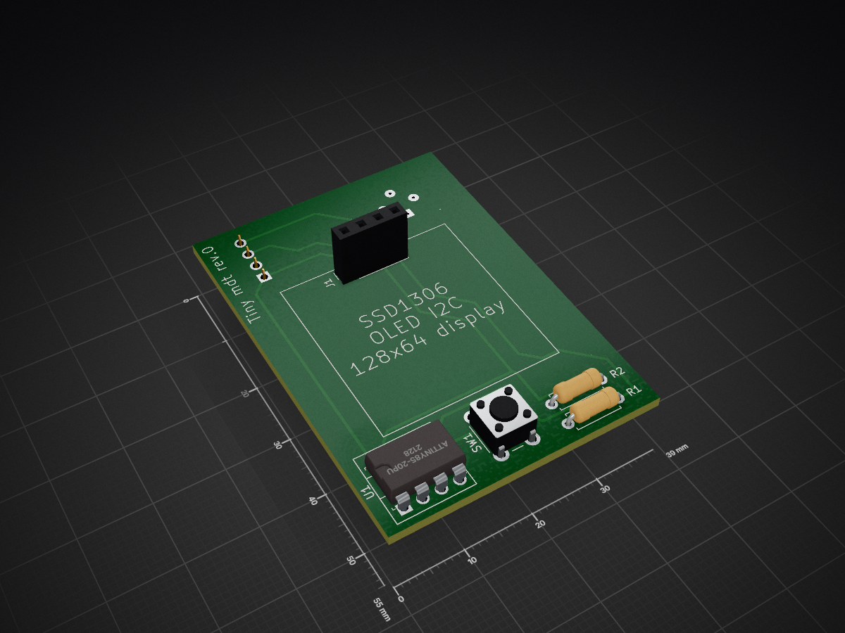
Tiny dt 0 is an open-source printed circuit board by Green-bms, from the Green-bms/Tiny_mdt repository on GitHub. It is a 2-layer board of 39 × 55 mm with 8 parts on 5 nets, routed with 93 tracks and 0 vias.
It is built around the ATTINY85-20PU and MLX90614ESF-BAA-000-TU. Its parts include 2 resistors, 2 ICs, 2 connectors and 1 switch. It belongs with the AVR (ATmega, ATtiny) boards of this library.


A useful tiny gadget!
Youtube video: https://www.youtube.com/embed/fY5Y1o6QoCc?si=GF92eTSO-mVCjJeZ
Tiny mdt is a small electronic gadget that measures environmental data and shows it on a small 0.96" OLED display.
The data is acquired and processed by an ATtiny85 microcontroller.
 )
The device is powered by a 3v CR2032 coin cell
the card only works when the power button is pressed and turns off when released.
So most of the time the device stays off, saving energy.
According to my calculations, with moderate use, the battery should last about 10-12 months.
I created the software with Arduino IDE. The big challenge was to find the lightest libraries to fit in the limited memory of the ATtiny85.
The project is available in 2 versions, with the same PCB (only the sensors to be used and the software to be loaded into the microcontroller change)
 )
This variant uses the HTU21D sensor which measures humidity and ambient temperature.
Furthermore, the temperature of an object is also detected using the MLX90614 infrared thermometer.
 )
 )
This is a small portable weather station in the palm of your hand!
The board uses the excellent BME280 sensor which measures humidity, temperature and barometric pressure.
 )
This project is completely open source and is very simple to create.
 )
I deliberately used tht components to facilitate soldering.
 )
The ATtiny85 microcontroller is socket mounted, so it can be easily removed and programmed using the maker's favorite programmer.
For example, I used the "Wemos as ISP" programmer that you find here: https://github.com/Green-bms/Wemos-as-ISP
 )
| Qty | Value | Footprint | References |
|---|---|---|---|
| 2 | 4.7K | Resistor_THT:R_Axial_DIN0207_L6.3mm_D2.5mm_P7.62mm_Horizontal | R1, R2 |
| 1 | VL53L0X time-of-flight distance sensor board | Connector_PinSocket_2.54mm:PinSocket_1x04_P2.54mm_Vertical | J2 |
| 1 | ATTINY85-20PU | digikey-footprints:DIP-8_W7.62mm | U1 |
| 1 | Battery Cell CR2032 | Battery:BatteryHolder_Keystone_3002_1x2032 | BT1 |
| 1 | MLX90614ESF-BAA-000-TU | digikey-footprints:TO-39-4 | U2 |
| 1 | SSD1306 OLED I2C 128x64 display | Connector_PinSocket_2.54mm:PinSocket_1x04_P2.54mm_Vertical | J1 |
| 1 | SW_Push_Dual | Button_Switch_THT:SW_PUSH_6mm | SW1 |
It measures 39 × 55 mm and has 2 copper layers, 1.6 mm thick.
8 parts, built around the ATTINY85-20PU and MLX90614ESF-BAA-000-TU. The full list of its parts is on this page, with links to each part's symbol and footprint where PCBKit's library has them.
From the Green-bms/Tiny_mdt repository on GitHub, at the commit this page was made from: the board is Kicad/tiny_dt_0/tiny_dt_0.kicad_pcb. PCBKit opens the board in the browser, with nothing to install.
Its repository states no licence, so its author keeps all rights: ask Green-bms before reusing the design.
Hazel-H-Chen/PocketSens
Microcontroller based sensor suite for portable environmental measurements.

lalithk06/PCB_Designs
This repository contains various PCB design projects made using KiCad


zeyad-hisham-cyper/Freelance-Projects
A portfolio of embedded systems, PCB design and IoT projects delivered for freelance clients and events, from schematic and PCB layout through firmware to companion mobile apps.

bwack/C64-Switchless-Multi-Kernal-27C256-adapter
Kernal switcher for the C64/C64C/C128

plusvic/simplebus2-intercom
General description of the Simplebus2 protocol used by some Comelit's intercoms. Hardware for retransmitting Simplebus2 messages over UART.