2 layers57 × 55.2 mm
LogicAnalyzer
gusmanb/logicanalyzer
24 channel, 100Msps logic analyzer hardware and software
10 parts5.1kGPL-3.0

 glasscake/Casio-CA-53W-Backlight7
This project is still very green, a rev A board has been produced and is being tested. significant redesigns are still needed to improve preformance and relability in assembly.
CA-53W backlight is an open-source printed circuit board by glasscake, from the glasscake/Casio-CA-53W-Backlight repository on GitHub. It is a 2-layer board of 19.6 × 21.3 mm with 10 parts on 6 nets, routed with 45 tracks and 13 vias.
Its parts include 4 resistors and 4 diodes.
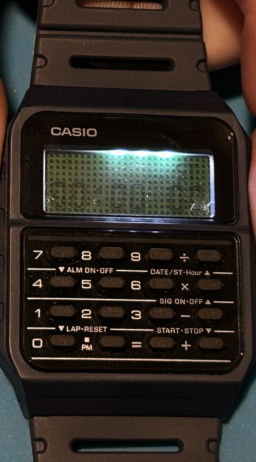
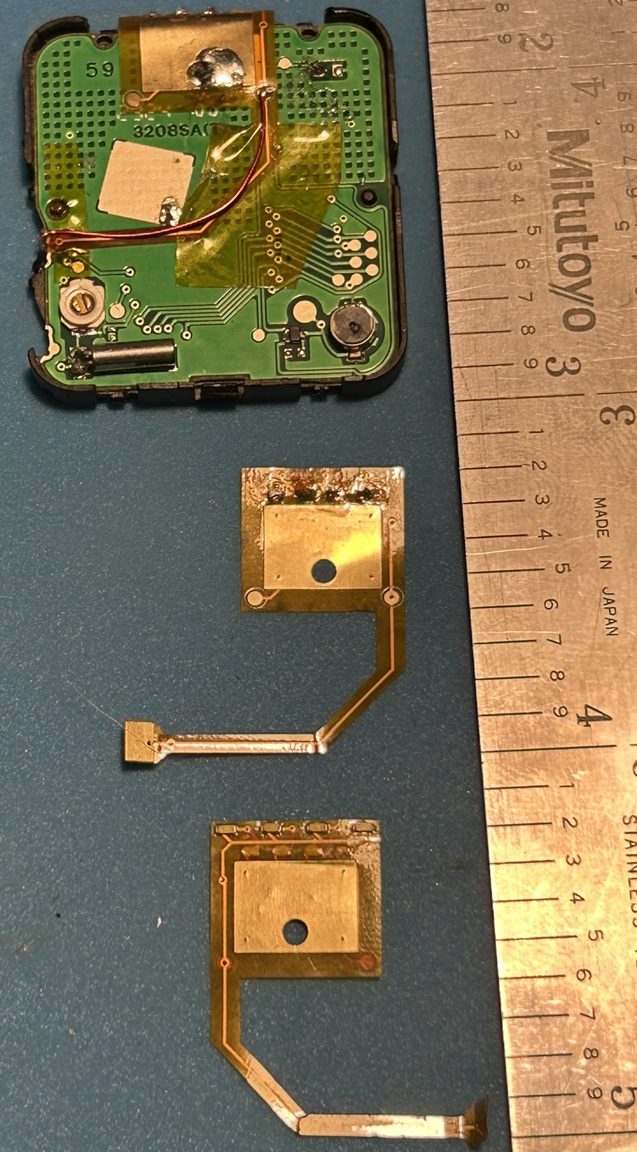
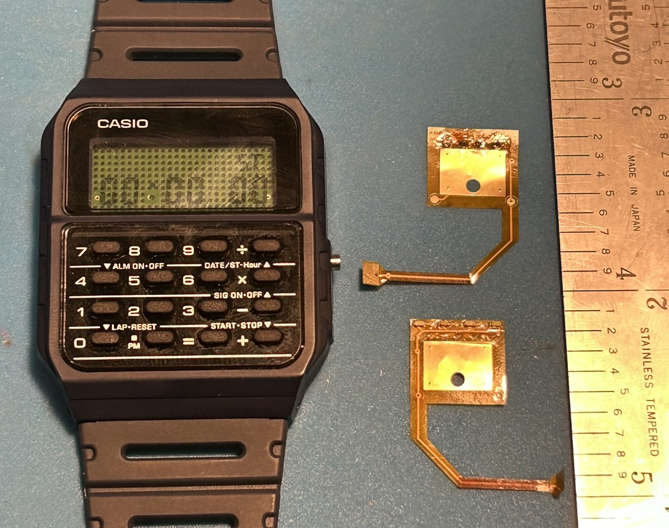
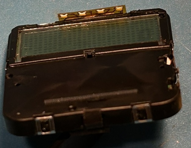
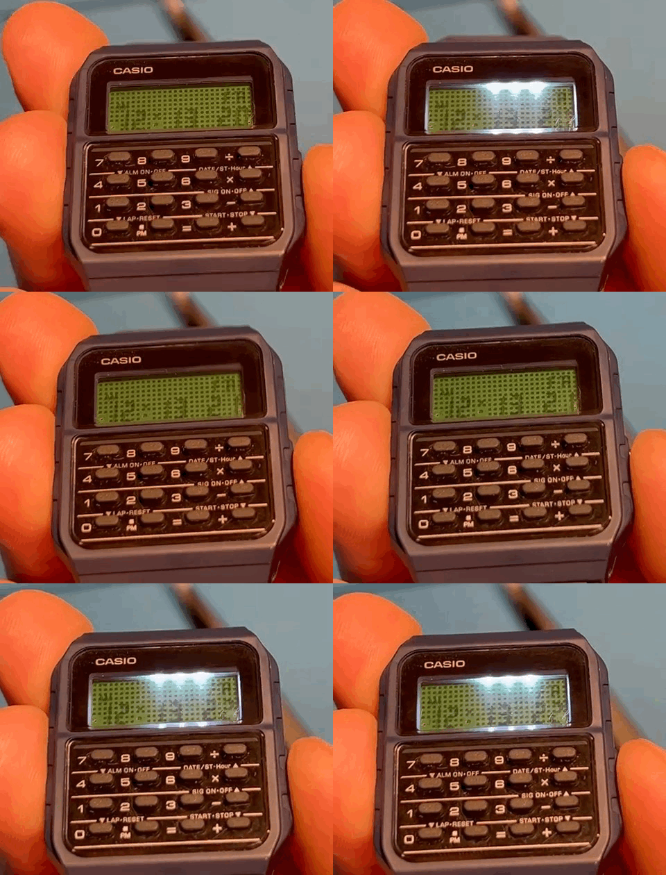

This is a PCB that adds backlight functonality to Casio-CA-53W style watches. It could potentially work with other Casio watches as well.
This project is still very green, a rev A board has been produced and is being tested. significant redesigns are still needed to improve preformance and relability in assembly. Watch the project and see how development goes.
The design files are made in KiCad an open source PCB design software.
Rev A boards have been produced from JLCPCB; uploading Rev A.zip to JLCPCB's or other PCB manufacturer's online portal and selecting flex PCB with ENIG sohuld get you boards similar to my own.
Once a suitable design has been found more thorough ordering instructions will be provided. The current design also has a stiffener, this has no benifit and is not required.
Current limiting resistors can be ommited if diodes with a foward voltage close to 3.0v are carefuly chosen. I am using Vishay VLMW15 serires 0402(imperial) LEDs at the moment.
These LEDs have a typical forward voltage of 2.9 volts which means when using the Casio's 3.0v battery the foward current is around 5mA very well within the 20mA rating of the componets. So shunts or solder bridges may be used instead.
0402 is the smallest componet the average enthusiast will be able to solder by hand so it was chosen for this project.
the move to 0201(imperial) LEDs may come if 0402 componets are too large to fit and retain splash resistance in the watch.
Copyright 2025 NuE All rights reserved
Private usage of this project by an individual with no intention to resell or distribute at profit the finished PCB, preassembled PCB, raw PCB, design files, or any item derived from this project is completly allowed.
At the moment this project is not open source. I am trying to figure out a license type that would allow contribution and private use but disallow an individual or company the ability to resell the componets, finished PCB, or design.
| Qty | Value | Footprint | References |
|---|---|---|---|
| 4 | LED | LED_SMD:LED_0402_1005Metric | D1, D2, D3, D4 |
| 4 | R | mine:402 jumper | R1, R2, R3, R4 |
| 2 | TestPoint | TestPoint:TestPoint_Pad_D1.0mm | TP1, TP2 |
gusmanb/logicanalyzer
24 channel, 100Msps logic analyzer hardware and software

byrantech/laptop
anyon_e, a highly integrated, high end, open source laptop. Attempt the impossible.

joeycastillo/Sensor-Watch
A board replacement for the classic Casio F-91W wristwatch


OLIMEX/OLINUXINO
OLINUXINO is Open Source / Open Hardware, low cost from EUR 24 Linux Industrial grade Single Board Computer capable to operate -25+85C

rusefi/rusefi
rusefi - GPL internal combustion engine control unit

VoronDesign/Voron-Hardware
Cool Hardware designed by the Voron Design group

hoglet67/RGBtoHDMI
Bare-metal Raspberry Pi project that provides pixel-perfect sampling of Retro Computer RGB/YUV video and conversion to HDMI
It measures 19.6 × 21.3 mm and has 2 copper layers, 1.6 mm thick.
10 parts. The full list of its parts is on this page, with links to each part's symbol and footprint where PCBKit's library has them.
From the glasscake/Casio-CA-53W-Backlight repository on GitHub, at the commit this page was made from: the board is PCB/CA-53W backlight.kicad_pcb and its schematic PCB/CA-53W backlight.kicad_sch. PCBKit opens the board in the browser, with nothing to install.
Its repository states no licence, so its author keeps all rights: ask glasscake before reusing the design.