

2 layers252.9 × 77.6 mm
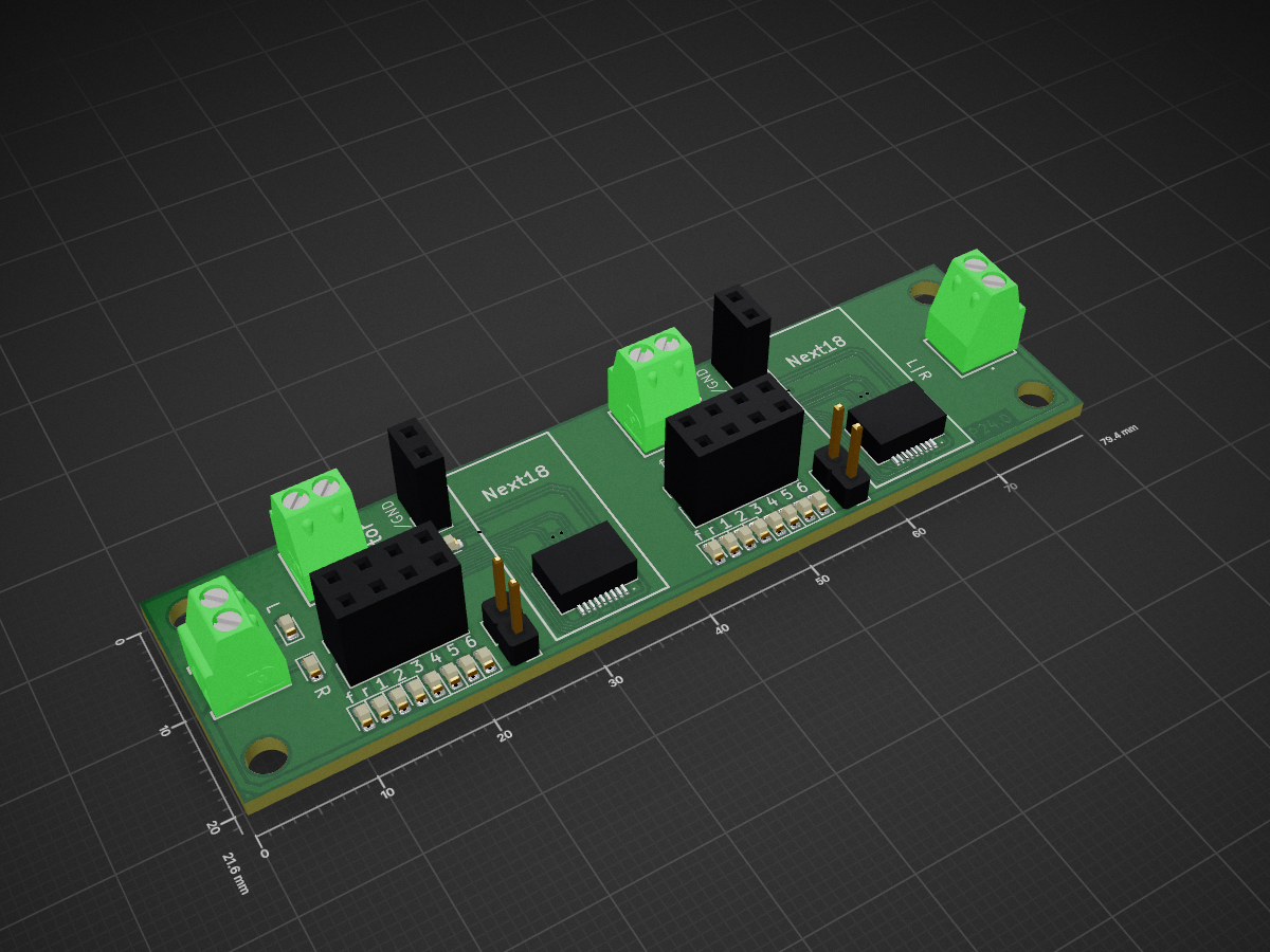
Dual Next18 decoder testing adapter
P24 is an open-source printed circuit board by git4dcc, from the git4dcc/RTB_P24 repository on GitHub, published under the Apache-2.0 licence. It is a 2-layer board of 79.4 × 21.6 mm with 58 parts on 50 nets, routed with 455 tracks and 52 vias.
Its parts include 22 resistors, 20 diodes and 12 connectors.


This simple module is a decoder test board with two Next18 sockets and is part of my growing collection of tools for my DCC based digital model trains. It has two independent Next18 sockets and the DCC signal is fed in and out at both ends to enable easy daisy chaining of multiple PCBs. For each, a motor or resistor can be connected externally to enable service mode programming with DCC.
<img src=supplemental/images/P24_main.jpg>
My PCB layout uses SMD footprints with mainly 0603 parts. Reflow soldering is my recommendation, but with some experience handsoldering is also possible.
<img src=supplemental/images/P24_top_connect.jpg>
:yellow_circle: Requires my Kicad project library RTB_SamacSys in the same directory tree.
<img src=supplemental/images/P24_usecase.jpg width=260>
This project is intended for hobby use only and is distributed in accordance with the Apache License 2.0 agreement.
| Qty | Value | Footprint | References |
|---|---|---|---|
| 20 | LED_Small_ALT | LED_SMD:LED_0603_1608Metric | D1, D2, D3, D4, D5, D10, D11, D12, D13, D14, D15, D16, D17, D18, D19, D20 +4 |
| 12 | 10k | Resistor_SMD:R_0603_1608Metric | R1, R2, R3, R4, R5, R6, R7, R8, R9, R10, R19, R20 |
| 8 | 2.2k | Resistor_SMD:R_0603_1608Metric | R11, R12, R13, R14, R15, R16, R17, R18 |
| 4 | MountingHole | MountingHole:MountingHole_3.2mm_M3_DIN965 | H1, H2, H3, H4 |
| 2 | 22 | Resistor_SMD:R_1206_3216Metric | R21, R22 |
| 2 | Conn_01x02 | Connector_PinHeader_2.54mm:PinHeader_1x02_P2.54mm_Vertical | J5, J8 |
| 2 | Conn_01x03_Male | RTB:1725656 | J11, J12 |
| 2 | Conn_01x03_Male | Connector_PinSocket_2.54mm:PinSocket_1x02_P2.54mm_Vertical | J3, J7 |
| 2 | Conn_01x08 | Connector_PinSocket_2.54mm:PinSocket_2x04_P2.54mm_Vertical | J1, J6 |
| 2 | Conn_02x09_Counter_Clockwise | RTB:AXK5F16547YG | J2, J4 |
| 2 | DCC | RTB:1725656 | J9, J10 |
It measures 79.4 × 21.6 mm and has 2 copper layers, 1.6 mm thick.
58 parts. The full list of its parts is on this page, with links to each part's symbol and footprint where PCBKit's library has them.
From the git4dcc/RTB_P24 repository on GitHub, at the commit this page was made from: the board is P24.kicad_pcb. PCBKit opens the board in the browser, with nothing to install.
Its repository publishes it under the Apache-2.0 licence: you may reuse it on that licence's terms (keep the author's notice, and for a copyleft licence share your changes alike).


zynthian/zynthian-hw
Zynthian hardware stuff: PCBs, schemes, parts specifications, pin assignment, ...


Hack-a-Day/2025-Communicator_Badge
The 2025 Hackaday Supercon RF Communicator Badge


rheslip/2HPico-Eurorack-Module-Hardware
2HP Eurorack module based on Raspberry Pi Pico 2

mck1117/wideband
The firmware/boards directory contains configuration for each board this firmware supports.