

6 layers17 × 10.9 mm
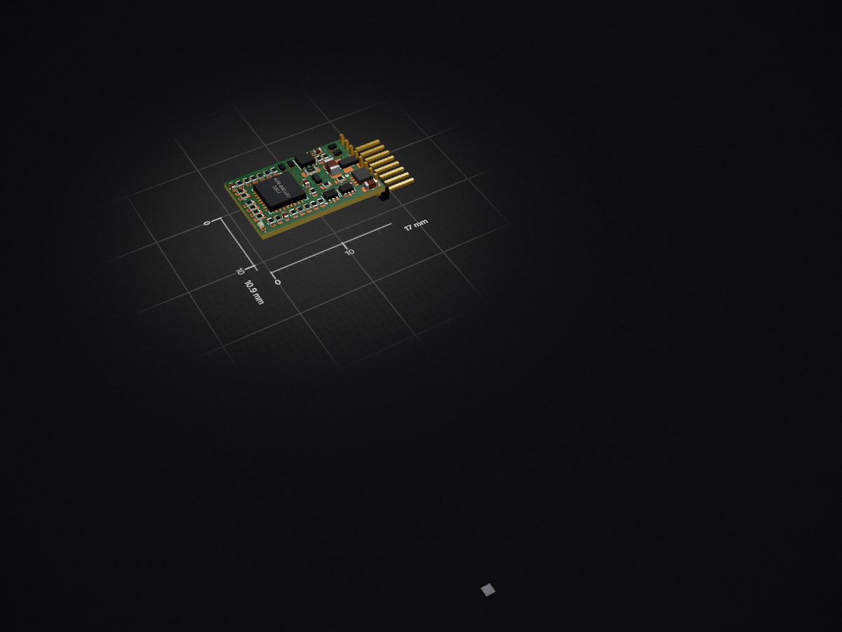
DCC / Railcom decoder (NEM651, single sided), WS28xx
D24 is an open-source printed circuit board by git4dcc, from the git4dcc/RTB_D24 repository on GitHub, published under the Apache-2.0 licence. It is a 6-layer board of 17 × 10.9 mm with 53 parts on 51 nets, routed with 382 tracks and 61 vias.
It is built around the AVR64DA32-E/PT, PMZB200UNEYL and BAS3007ARPPE6327HTSA1, with the BC847BDW1 and BC857BDW1 among its other parts. Its parts include 25 resistors, 9 connectors, 6 capacitors, 6 transistors and 3 ICs.


My Homebrew D24 is a single-sided DIY mobile decoder featuring a NEM-651 connector. While it shares the exact same dimensions as the D16, it offers additional AUX channels and supports WS28xx LED connections. It is fully designed for integration into the RTB digital control ecosystem.
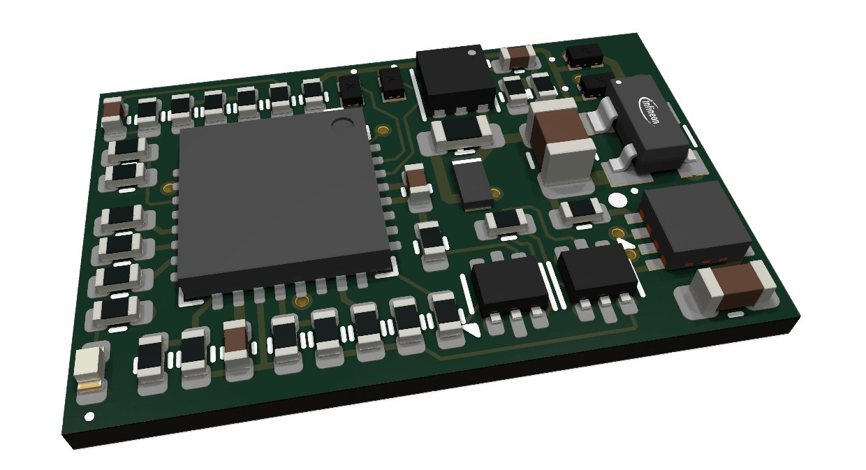
The decoder has the following features,
The current PCB layout uses SMD footprints with 0.5mm pitch and mainly 0402 parts. Reflow soldering is recommended, handsoldering will be difficult.
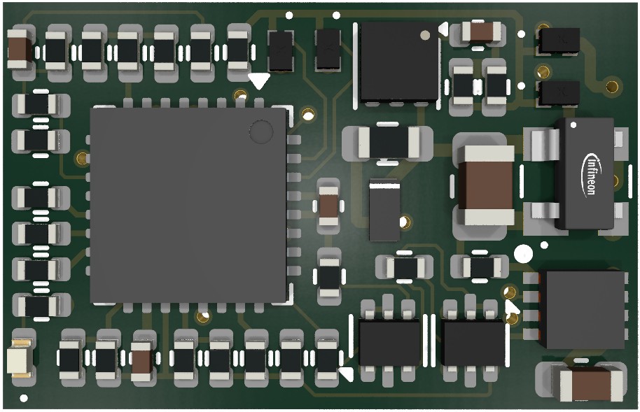
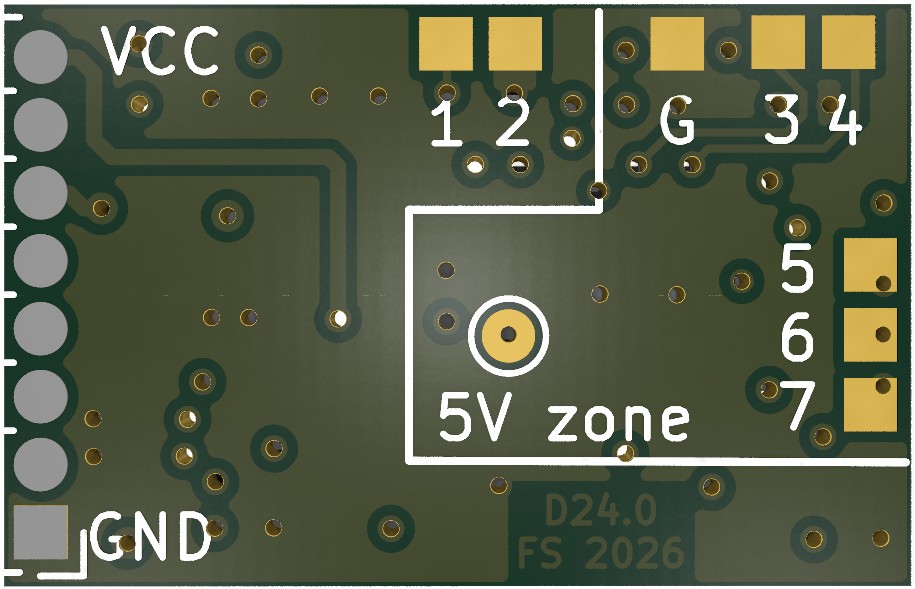
Note: The '5V zone' silk text can be misleading as the above test point is not 5V source but rather the UPDI interface.
:yellow_circle: Requires my Kicad project library RTB_SamacSys in the same directory tree.
Filename structure: { pcb }{ code }{ version }.hex
Example: D16F0001.hex
| Description | |
|---|---|
| pcb | Name of matching hardware (D24) |
| code | Type of code contained (R=rom, B=bootloader, F=flash, U=bld update, P=UPDI factory code) |
| version | Release version (####) |
| top | bottom |
|---|---|
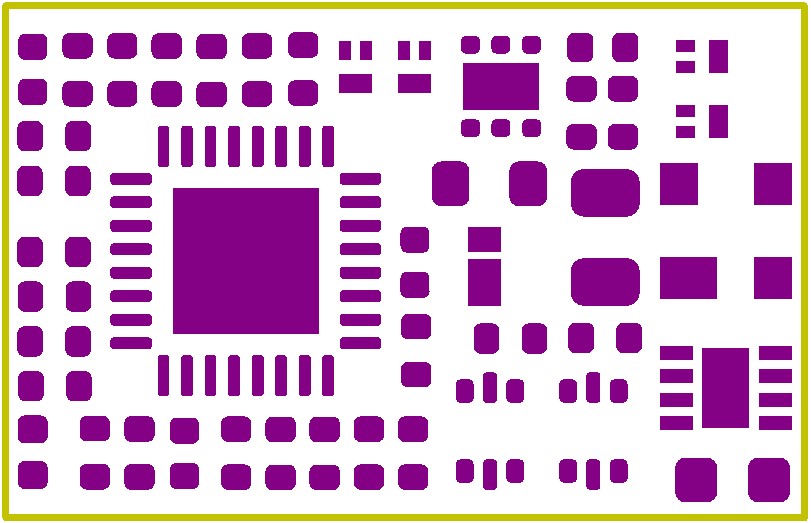 | 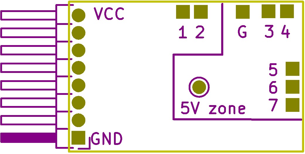 |
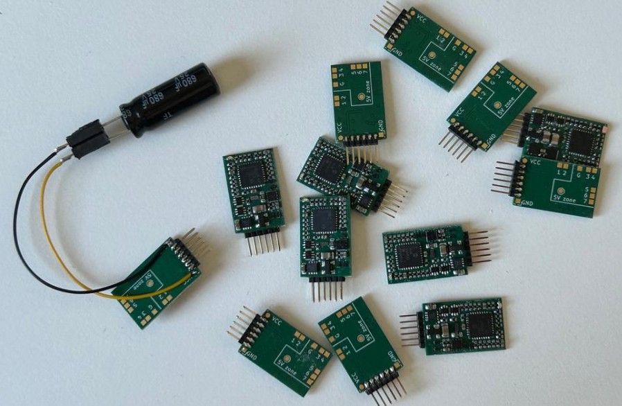
Some YouTubes to see the D24 decoder in action.
This project is intended for hobby use only and is distributed in accordance with the Apache License 2.0 agreement.
| Qty | Value | Footprint | References |
|---|---|---|---|
| 6 | 10k | Resistor_SMD:R_0402_1005Metric | R11, R13, R15, R18, R19, R20 |
| 5 | Conn_01x01 | RTB:Solder_Pad_1.0x1.0mm | J1, J3, J4, J5, J6 |
| 4 | 33k | Resistor_SMD:R_0402_1005Metric | R7, R8, R10, R12 |
| 4 | 4.7k | Resistor_SMD:R_0402_1005Metric | R1, R4, R5, R6 |
| 4 | PMZB200UNEYL | RTB:PMZB200UNEYL | Q2, Q3, Q5, Q6 |
| 3 | 10u/6.3V | Capacitor_SMD:C_0402_1005Metric | C1, C3, C13 |
| 3 | 220k | Resistor_SMD:R_0402_1005Metric | R17, R34, R35 |
| 2 | 2.2 | Resistor_SMD:R_0402_1005Metric | R9, R22 |
| 2 | 9.1k | Resistor_SMD:R_0402_1005Metric | R36, R37 |
| 1 | 100 | Resistor_SMD:R_0603_1608Metric | R14 |
| 1 | 1k | Resistor_SMD:R_0402_1005Metric | R21 |
| 1 | 1u | Capacitor_SMD:C_0402_1005Metric | C6 |
| 1 | 1u/35V | Capacitor_SMD:C_0603_1608Metric | C4 |
| 1 | 22 | Resistor_SMD:R_0402_1005Metric | R3 |
| 1 | 22u/25V | Capacitor_SMD:C_0805_2012Metric | C7 |
| 1 | 3.3k | Resistor_SMD:R_0402_1005Metric | R2 |
| 1 | AVR-64DA32 | Package_DFN_QFN:VQFN-32-1EP_5x5mm_P0.5mm_EP3.1x3.1mm | U1 |
| 1 | BAS3007ARPPE6327HTSA1 | RTB:BF998215 | D3 |
| 1 | BC847BDW1 | Package_TO_SOT_SMD:SOT-666 | Q1 |
| 1 | BC857BDW1 | Package_TO_SOT_SMD:SOT-666 | Q4 |
| 1 | DRV8231ADSGR | RTB:SON50P200X200X80-9N | IC1 |
| 1 | LED pink | LED_SMD:LED_0402_1005Metric | D1 |
| 1 | NCP730BMT500TBG | Package_SON:WSON-6-1EP_2x2mm_P0.65mm_EP1x1.6mm_ThermalVias | IC2 |
| 1 | NEM651 | Connector_PinHeader_1.27mm:PinHeader_1x08_P1.27mm_Horizontal | J2 |
| 1 | NSR20F40NXT5G | RTB:NSR20F40NXT5G | D2 |
| 1 | TestPoint | TestPoint:TestPoint_Pad_D1.0mm | TP1 |
| 1 | WS28xx GND | RTB:Solder_Pad_1.0x1.0mm | J8 |
| 1 | WS28xx data | RTB:Solder_Pad_1.0x1.0mm | J7 |
| 1 | WS28xx power | RTB:Solder_Pad_1.0x1.0mm | J9 |
It measures 17 × 10.9 mm and has 6 copper layers, 0.8 mm thick.
53 parts, built around the AVR64DA32-E/PT, PMZB200UNEYL, BAS3007ARPPE6327HTSA1 and BC847BDW1. The full list of its parts is on this page, with links to each part's symbol and footprint where PCBKit's library has them.
From the git4dcc/RTB_D24 repository on GitHub, at the commit this page was made from: the board is D24.kicad_pcb and its schematic D24.kicad_sch. PCBKit opens the board in the browser, with nothing to install.
Its repository publishes it under the Apache-2.0 licence: you may reuse it on that licence's terms (keep the author's notice, and for a copyleft licence share your changes alike).


