2 layers99.1 × 99.1 mm
100x100mm Computer Perf Board
giraffeics/BEEBA
An 8-bit computer built using 7400 Series discrete logic chips.
1,283 parts2
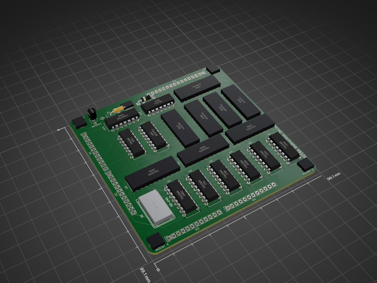
 giraffeics/BEEBA2
An 8-bit computer built using 7400 Series discrete logic chips.
Instruction Decoder is an open-source printed circuit board by giraffeics, from the giraffeics/BEEBA repository on GitHub. It is a 2-layer board of 99.1 × 99.1 mm with 50 parts on 134 nets, routed with 1,846 tracks and 35 vias.
It is built around the 74LS373SC, 74LS193P-E and 74HCT04D, with the 74LS04PC and 74LS74PC among its other parts. Its parts include 18 capacitors, 18 ICs, 1 resistor, 1 diode and 1 transistor. It belongs with the retro computing and games boards of this library.


An 8-bit computer built using 7400 Series discrete logic chips.
The "CAD" folder contains all design files for the printed circuit boards. These are KiCAD documents. The "Assembler" folder contains the C++ source code for the assembler, as well as the list of register names and some programs written in BEEBA assembly language. The assembler can be compiled with MinGW on Windows, and has not been tested on other compilers or operating systems.
Assembly language programs can be in any plain-text file format. The language is not case-sensitive. Each instruction copies eight bits of data from one register location to another. A line of code can follow one of three formats:
Reads one byte of data from the register specified by [read location], writes data to the register specified by [write location].
Writes a byte of data specified by [data] to the register specified by [write location]. [data] can be a two-digit hexadecimal number or a marker.
Marks the instruction position that corresponds to the following line of code. This does not represent an actual instruction. [marker name] can be referenced by SET instructions before or after the location of the marker, using a colon to specify which byte of the marker's location to use. This ranges from 0 (least significant) to 2 (most significant).
For all of these, any text after the last parameter will be ignored. However, it must be separated by a space or tab from the last parameter.
Register names are listed in REGISTER_NAMES.txt. The assembler uses this file to convert names to addresses while compiling programs.
To use the assembler, simply drag assembly source files onto the compiled executable.
As BEEBA uses two physical ROM chips to store 16-bit-wide instructions, the assembler will output two .bin files. One of these is loaded onto the ROM chip on the left, the other is loaded onto the ROM chip on the right. They are named accordingly.
When writing a constant to a register, the value will be corrupted unless the same data is sent to another register in the next instruction. The current workaround is to send data to NULL, which is an unused register.
The NES controller interface board cannot read the state of the A button. Pannenkoek2012 would love this.
The "Basic IO Board"'s input does not work at all. This was caused by oversights during the transition from TTL to CMOS. Output is still fully functional.
| Qty | Value | Footprint | References |
|---|---|---|---|
| 18 | 10µF | Capacitors_SMD:C_1206_HandSoldering | C1, C2, C3, C4, C5, C6, C7, C10, C11, C12, C13, C14, C15, C16, C17, C18 +2 |
| 7 | 74LS373 | Housings_DIP:DIP-20_W7.62mm | U8, U9, U10, U12, U13, U15, U17 |
| 6 | 74LS193 | Housings_DIP:DIP-16_W7.62mm | U1, U2, U3, U4, U5, U6 |
| 4 | 1pin | Connect:1pin | MOUNT 1, MOUNT 2, MOUNT 3, MOUNT 4 |
| 4 | CONN_01X12 | Socket_Strips:Socket_Strip_Straight_1x12 | H1, H2, H3, H4 |
| 1 | 2N3904 | TO_SOT_Packages_THT:TO-92_Inline_Wide | Q1 |
| 1 | 2N5060 | thyristor:TO-92_Inline_Wide | T1 |
| 1 | 4.7kΩ | Resistors_ThroughHole:Resistor_Horizontal_RM10mm | R1 |
| 1 | 74HCT04 | Housings_DIP:DIP-14_W7.62mm | U14 |
| 1 | 74LS04 | Housings_DIP:DIP-14_W7.62mm | U7 |
| 1 | 74LS138 | Housings_DIP:DIP-16_W7.62mm | U11 |
| 1 | 74LS244 | Housings_DIP:DIP-20_W7.62mm | U16 |
| 1 | 74LS74 | Housings_DIP:DIP-14_W7.62mm | U18 |
| 1 | CONN_01X16 | Socket_Strips:Socket_Strip_Straight_1x16 | H5 |
| 1 | D | Diodes_ThroughHole:Diode_DO-41_SOD81_Horizontal_RM10 | D1 |
| 1 | XO-14S | xo_14s:XO-14S | X1 |
It measures 99.1 × 99.1 mm and has 2 copper layers, 1.6 mm thick.
50 parts, built around the 74LS373SC, 74LS193P-E, 74HCT04D and 74LS04PC. The full list of its parts is on this page, with links to each part's symbol and footprint where PCBKit's library has them.
From the giraffeics/BEEBA repository on GitHub, at the commit this page was made from: the board is CAD/Instruction Decoder MK2/Instruction Decoder.kicad_pcb. PCBKit opens the board in the browser, with nothing to install.
Its repository states no licence, so its author keeps all rights: ask giraffeics before reusing the design.
giraffeics/BEEBA
An 8-bit computer built using 7400 Series discrete logic chips.

giraffeics/BEEBA
An 8-bit computer built using 7400 Series discrete logic chips.

giraffeics/BEEBA
An 8-bit computer built using 7400 Series discrete logic chips.

giraffeics/BEEBA
An 8-bit computer built using 7400 Series discrete logic chips.

giraffeics/BEEBA
An 8-bit computer built using 7400 Series discrete logic chips.

giraffeics/BEEBA
An 8-bit computer built using 7400 Series discrete logic chips.

giraffeics/BEEBA
An 8-bit computer built using 7400 Series discrete logic chips.

giraffeics/BEEBA
An 8-bit computer built using 7400 Series discrete logic chips.

giraffeics/BEEBA
An 8-bit computer built using 7400 Series discrete logic chips.

giraffeics/BEEBA
An 8-bit computer built using 7400 Series discrete logic chips.

giraffeics/BEEBA
An 8-bit computer built using 7400 Series discrete logic chips.

ceteras/Cobra-XP
Derived from Cobra, an experimental board for testing all kind of mods.

misterblack1/zenith_zt1
Information gathered on the Zenith ZT-1 / ZT-10 / ZT-11 and ZTX/ZT-x-A variants

robertrico/dino-homebrew
A perfboard with the bus edge and the slot decode every DINO card repeats. Plug it into any of J1-J8 on the Rev 1.0 mainboard, pick the slot with one shunt, bodge the card on the grid.


schenkmi/electronic-retro-computing-projects
In revision 2, the PCB size has been reduced by more than 50% and TAPuino support has been ditched. It now features a Micro SD slot and a few other improvements.

osiweb/unified_retro_keyboard
Project to provide keyboard replacements for various classic computers, as well as classic ASCII keyboard

nmikstas/atari-avg-replacements
Atari AVG chip replacements. Both CPLD andTTL versions of the chip.
