2 layers65 × 85 mm

 gibbi/PicoGPSDO23
Hardware and Software for the PicoGPSDO
ResamplerBoard is an open-source printed circuit board by gibbi, from the gibbi/PicoGPSDO repository on GitHub. It is a 2-layer board of 70 × 55 mm with 23 parts on 38 nets, routed with 39 tracks and 7 vias.
Its parts include 8 resistors, 2 capacitors and 1 IC. It belongs with the RP2040 boards of this library.
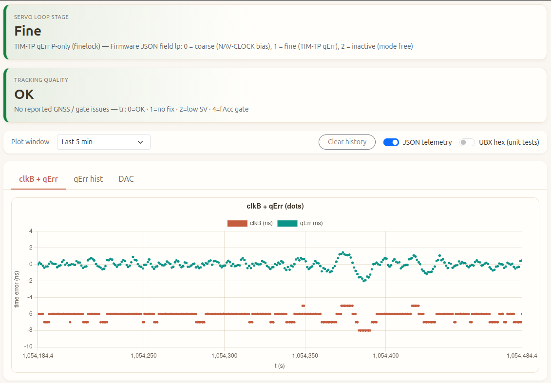
RP2040 firmware that steers an OCXO via PWM (“DAC”), reads u-blox GNSS time over UART (UBX), and closes a two-stage servo: coarse steering from NAV-CLOCK and fine steering from TIM-TP qErr. A small Flask dashboard on the host tails USB CDC for live plots and tuning.
Hardware upstream: this tree is based on gibbi/PicoGPSDO (schematics, KiCad, and notes under hardware/). Presentation context: European GNU Radio Days 2024 — talk on YouTube.
| Area | Role |
|---|---|
src/main.c | Boot, PWM DAC / 26 MHz ref clock, main loop, JSON telemetry, USB CLI polling, fine-mode edge tracker integration, fractional DAC accumulation. |
src/ubx.c, src/ubx_rx.c | UART RX (frame assembly + checksum), UBX decode, fills current_gps_data (NAV-CLOCK, TIM-TP, PVT, etc.). |
include/ubx_clean.h | Shared GPS/UBX structs and packet layout used by the parser. |
src/gpsdo_control.c, include/gpsdo_control.h | Finelock hysteresis, coarse/fine control outputs (u_ns), NAV-CLOCK bias handling, telemetry tr flags. |
src/gpsdo_tune.c, include/gpsdo_tune.h | Runtime tunables and USB one-line CLI (kp, fine_mode, gates, etc.). |
include/display.h | SSD1306 OLED over I2C (optional); live status text on the module. |
pico_gpsdo_web.py | Flask host app: reads Pico USB serial, parses {…} telemetry, serves charts, tune forms, log tail, optional series clear. |
pico.py | Developer entrypoint: clean / build / flash / webserver / lint (see script header for caveats on build/ paths). |
CMakeLists.txt, boards/ | Pico SDK project, board hooks. |
hardware/ | From PicoGPSDO: PCB and hardware documentation (see hardware/Readme.md). |
tests/ | Small host-side tests (e.g. UBX RX framing). |
current_gps_data (clkB, qErr, dac, fix, etc.).mode servo): coarse on clkD_bias when bias steps; fine on qErr (P-only or edge mode) in finelock.printf debugging.# Firmware (needs Pico SDK in environment per Pico docs)
./pico.py build
./pico.py flash # optional: ./pico.py flash --webserver
# Web dashboard only (USB serial to the Pico)
pip install -r requirements.txt
./pico.py webserver # or: python3 pico_gpsdo_web.py … per pico.py usage| Qty | Value | Footprint | References |
|---|---|---|---|
| 4 | 330 | Resistor_SMD:R_1210_3225Metric_Pad1.30x2.65mm_HandSolder | R1, R2, R3, R4 |
| 3 | R | Resistor_SMD:R_1210_3225Metric_Pad1.30x2.65mm_HandSolder | R6, R7, R8 |
| 2 | C | Capacitor_SMD:C_1210_3225Metric_Pad1.33x2.70mm_HandSolder | C1, C2 |
| 2 | TestPoint | TestPoint:TestPoint_Pad_D2.0mm | 5V_TP1, PPS_TP1 |
| 1 | 26MHz | gibbi_custom:SMA_EDGE_GIBBI | 26MHzOut1 |
| 1 | 47 | Resistor_SMD:R_1210_3225Metric_Pad1.30x2.65mm_HandSolder | R5 |
| 1 | 9600 | gibbi_custom:GPS_HEADER | GPS_UART1 |
| 1 | Conn_01x02_Pin | gibbi_custom:PinHeader_1x02_5VIN | 5VCCin1 |
| 1 | ExtRef | gibbi_custom:SMA_EDGE_GIBBI | ExtRef1 |
| 1 | OLED_CONN | SSD1306:128x64OLED | I2C1 |
| 1 | PWM | gibbi_custom:SMA_EDGE_GIBBI | PWM1 |
| 1 | Pico | gibbi_custom:RPi_Pico_SMD_TH_NO_SILK_NO_HOLE | U1 |
The 19 most common of 23 parts.


google/mozc-devices
Circuit diagrams and firmware source code for Gboard DIY keyboards


Duet3D/Duet-2-Hardware
The KiCAD source for the Duet 3d printer controller see www.duet3d.com
It measures 70 × 55 mm and has 2 copper layers, 1.6 mm thick.
23 parts. The full list of its parts is on this page, with links to each part's symbol and footprint where PCBKit's library has them.
From the gibbi/PicoGPSDO repository on GitHub, at the commit this page was made from: the board is hardware/ResamplerBoard/ResamplerBoard.kicad_pcb and its schematic hardware/OCXOBoard/OCXOBoard.kicad_sch. PCBKit opens the board in the browser, with nothing to install.
Its repository states no licence, so its author keeps all rights: ask gibbi before reusing the design.