
2 layers24.1 × 30.5 mm
A500MPU Adapter
gianlucarenzi/stalker
STM32 Usb Based firmware microcontroller for any Amiga internal keyboard adapter
15 parts47

 gianlucarenzi/stalker47
STM32 Usb Based firmware microcontroller for any Amiga internal keyboard adapter
StandAlone Adapter is an open-source printed circuit board by gianlucarenzi, from the gianlucarenzi/stalker repository on GitHub. It is a 2-layer board of 78.7 × 58.4 mm with 60 parts on 77 nets, routed with 542 tracks and 23 vias.
It is built around the BSS138. Its parts include 15 resistors, 14 capacitors, 11 connectors, 3 transistors and 2 ICs. It belongs with the interfaces and adapters and keyboards and input boards and the STM32 boards of this library.
The STALKER adapter board enables connecting USB HID keyboards to your Amiga 1000, Amiga 2000/3000, Amiga 4000/CD32, Amiga 500, Amiga 1200 and Amiga 600 and it is based upon 32-bit STM32 microcontroller.
The STALKER provides built-in USB stack which enables USB HID keyboards support without the need for installing additional AmigaOS software drivers. The whole installation process comes down to simply connecting a STALKER adapter and plug to the keyboard port of your Amiga 1000, 2000 or 4000 externally, or internally in any other Amiga computers.
Additional feature of the adapter is its „Bootloader” function allowing future firmware upgrades. The STALKER comes with dedicated firmware, but it can be easily installed any firmware version as it's an open source project.
Why so a bad name for a so good product?
As stated in the title, the STALKER is an acronym of:
But if you think a little more, it is catching all the keystrokes you do,
so basically it is stalking you! ;-)
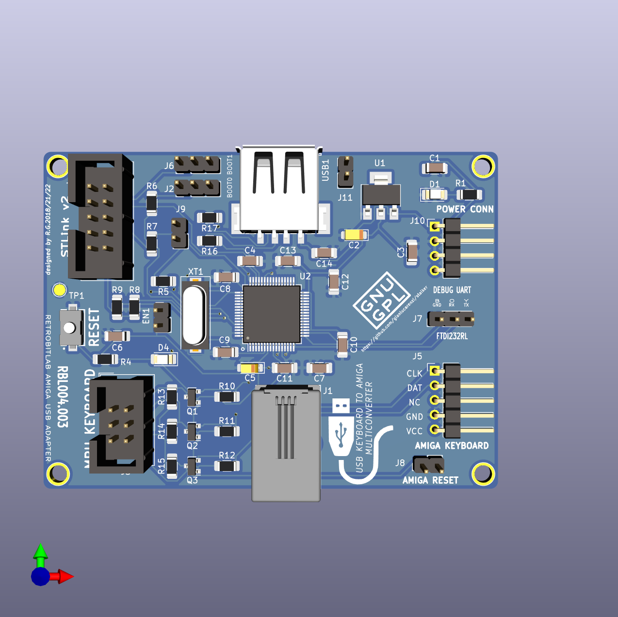
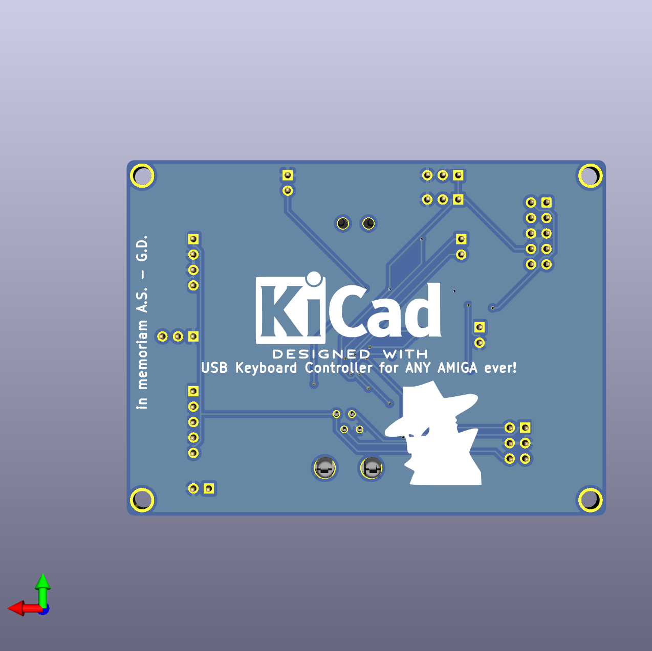
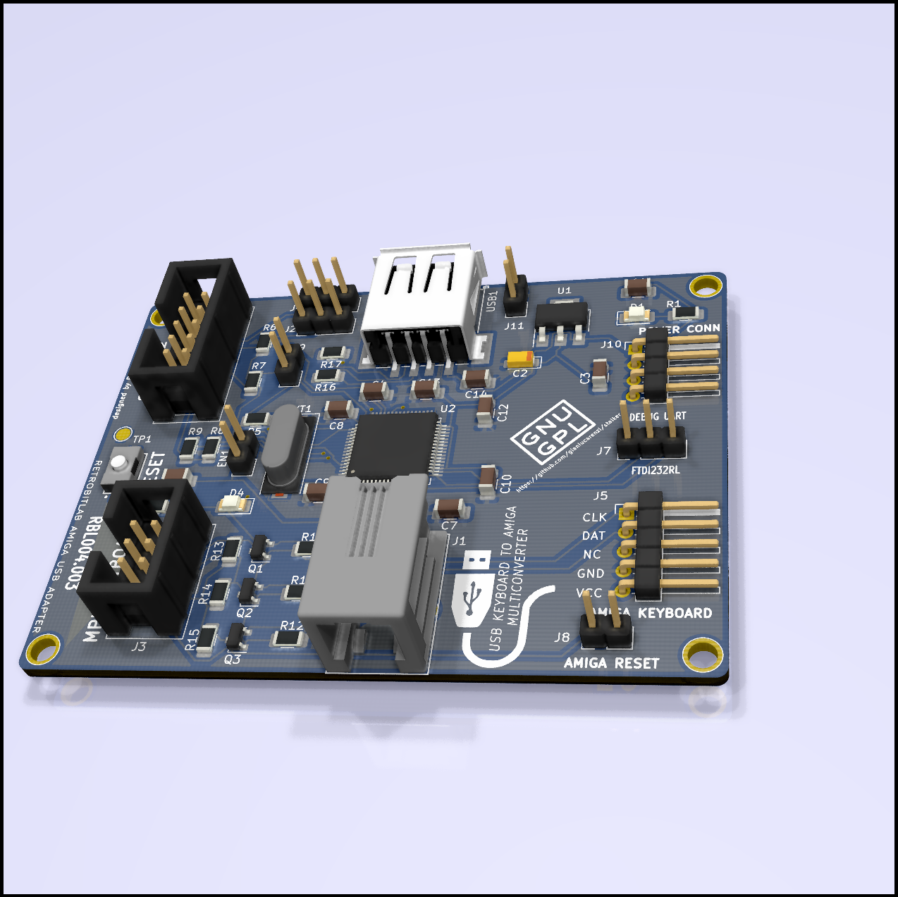
Starting from this project folder, there are some shell scripts that can be used to program the board if you unluckly brick it or simply to upgrade some features from bootloader and application without using the STM32CubeProgrammer software.
Connect the STLinkV2 jtag/swd programmer to the STALKER Board in J4 connector (STLink V2 in the silkscreen) using a standard 10 pin IDC female/female cable 2x5 10P. Opening the project folder, you can compile all projects (application and bootloader) running:
make clean
make
and then launch the corresponding script:
bootloader.sh (to erase all the flash memory and program the bootloader)
flash.sh (to program the application, after having erased all needed flash sectors)
First, get your own copy of STM32CubeProgrammer software. It is free to use, please checkout the STMicroElectronics web site and install it into your PC. Please have a look at the following web link: https://www.st.com/en/development-tools/stm32cubeprog.html
After launched it will be shown as the following image.

Connect the special upgrade cable to the right lower opening of The STALKER, then connect the board with the provided USB cable to the one of the USB ports available in your computer. The red LED will light steady.
Then click on the connect button on the upper right position of the STM32Cube Programmer's window as shown in the picture below:

Some information will be shown into the right bottom side of the same window, plus the memory locations will be filled up by the programmed values.

After, you will need to select the correct FIRMWARE file (.hex file format) clicking into the Open File tab button like in the following example:
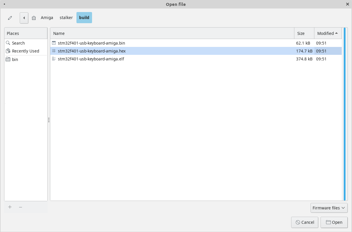
If the file is loaded correctly, the Download button needs to be pressed to start the programming/flashing procedure. It will takes few seconds to be completed.

The firmware is correctly installed into the board, and it can be used as usual.

Now you can:
That's all folks!
Copyright (C) 2018/2019/2022/2023/2025 Gianluca Renzi gianlucarenzi@eurek.it icjtqr@gmail.com
The hardware of this project is released as free/open hardware under the GNU GPL v3 License terms. See licence.txt for details.
| Qty | Value | Footprint | References |
|---|---|---|---|
| 11 | 10K | Resistor_SMD:R_1206_3216Metric_Pad1.30x1.75mm_HandSolder | R4, R6, R7, R8, R9, R10, R11, R12, R13, R14, R15 |
| 8 | 100n | Capacitor_SMD:C_1206_3216Metric_Pad1.33x1.80mm_HandSolder | C3, C4, C6, C10, C11, C12, C13, C14 |
| 4 | CONN_01X01 | RetroBitLab:MountingHole | H1, H2, H3, H4 |
| 3 | BSS138 | Package_TO_SOT_SMD:SOT-23 | Q1, Q2, Q3 |
| 3 | Conn_01x02 | Connector_PinHeader_2.54mm:PinHeader_1x02_P2.54mm_Vertical | J8, J9, J11 |
| 3 | Conn_01x03 | Connector_PinHeader_2.54mm:PinHeader_1x03_P2.54mm_Vertical | J2, J6, J7 |
| 2 | 22R | Resistor_SMD:R_1206_3216Metric_Pad1.30x1.75mm_HandSolder | R16, R17 |
| 2 | 22pF | Capacitor_SMD:C_1206_3216Metric_Pad1.33x1.80mm_HandSolder | C8, C9 |
| 2 | 330R | Resistor_SMD:R_1206_3216Metric_Pad1.30x1.75mm_HandSolder | R1, R5 |
| 2 | RED | LED_SMD:LED_1206_3216Metric_Pad1.42x1.75mm_HandSolder | D1, D4 |
| 1 | 100nF | Capacitor_SMD:C_1206_3216Metric_Pad1.33x1.80mm_HandSolder | C1 |
| 1 | 10u | Capacitor_Tantalum_SMD:CP_EIA-3216-18_Kemet-A_Pad1.58x1.35mm_HandSolder | C5 |
| 1 | 10uF | Capacitor_Tantalum_SMD:CP_EIA-3216-12_Kemet-S_Pad1.58x1.35mm_HandSolder | C2 |
| 1 | 4.7uF | Capacitor_SMD:C_1206_3216Metric_Pad1.33x1.80mm_HandSolder | C7 |
| 1 | 8Mhz | Crystal:Crystal_SMD_HC49-SD | XT1 |
| 1 | AZ1117-3.3 | Package_TO_SOT_SMD:SOT-223 | U1 |
| 1 | CONN_01X02 | Connector_PinHeader_2.54mm:PinHeader_1x02_P2.54mm_Vertical | EN1 |
| 1 | Conn_01x04 | Connector_PinHeader_2.54mm:PinHeader_1x04_P2.54mm_Horizontal | J10 |
| 1 | Conn_01x05 | Connector_PinHeader_2.54mm:PinHeader_1x05_P2.54mm_Horizontal | J5 |
| 1 | Conn_02x03_Odd_Even | RetroBitLab:IDC-Header_2x03_P2.54mm_Vertical | J3 |
| 1 | GND | TestPoint:TestPoint_Pad_D2.0mm | TP1 |
| 1 | GPL | Symbol:KiCad-Logo2_12mm_SilkScreen | LOGO2 |
| 1 | JTAG SWDIO SWCLK | Connector_IDC:IDC-Header_2x05_P2.54mm_Vertical | J4 |
| 1 | RJ10 | RetroBitLab:RJ10-RECEPTACLE-Assmann-ASS-2004-3-4-LP-N-R | J1 |
| 1 | STALKER! | RetroBitLab:Symbol_GNU-GPL_SilkScreen_Small | LOGO3 |
| 1 | STM32F401RBTx | Package_QFP:LQFP-64_10x10mm_P0.5mm | U2 |
| 1 | SW_PUSH | RetroBitLab:SPST-7.3x3.9x2.5-WUERTH-434121025816 | RESET1 |
| 1 | Stalker Logo | RetroBitLab:Stalker_16.1x17.3mm | LOGO4 |
| 1 | USB | RetroBitLab:USB_PLUG_15x15mm | LOGO1 |
| 1 | USB_A_SMD_LCSC | RetroBitLab:USB_A_M04P-F000_LCSC_C386738 | USB1 |
gianlucarenzi/stalker
STM32 Usb Based firmware microcontroller for any Amiga internal keyboard adapter

gianlucarenzi/stalker
STM32 Usb Based firmware microcontroller for any Amiga internal keyboard adapter

gianlucarenzi/stalker
STM32 Usb Based firmware microcontroller for any Amiga internal keyboard adapter

StuckAtPrototype/Racer
These are structured into their own files. I could have used submodules, but decided against it.

willem-pennings/balancing-cube
A cube that balances itself in a corner or edge using reaction wheels

abhishek-kakkar/BeagleLogic
A Software Suite that implements a logic analyzer with the PRU on the BeagleBone / BeagleBone Black.


lachlanA/eagle-to-kicad
Eagle SCH/LIB to KiCad SCH/LIB ULP conversion script

No0ne/ps2x2pico
USB keyboard/mouse to PS/2 interface converter using a Raspberry Pi Pico

StuckAtPrototype/AirCube
Works standalone out of the box. Pairs with Home Assistant in minutes. Other platforms are supported through community-contributed extensions.

It measures 78.7 × 58.4 mm and has 2 copper layers, 1.6 mm thick.
60 parts, built around the BSS138. The full list of its parts is on this page, with links to each part's symbol and footprint where PCBKit's library has them.
From the gianlucarenzi/stalker repository on GitHub, at the commit this page was made from: the board is hw/AmigaKeyboardAdapters/StandAlone-Adapter/StandAlone-Adapter.kicad_pcb. PCBKit opens the board in the browser, with nothing to install.
Its repository states no licence, so its author keeps all rights: ask gianlucarenzi before reusing the design.